"Do you still play that Starcraft game you used to play in 4th grade?" asked a middle school friend I hadn't seen in a while. Wasn't the first time I heard something pertaining to both Starcraft/me in my early days. Starcraft/Brood war was my first love, and had a big impact on me
.
I played it to death, never really got better at it over the years, but oh lawrd was it fun. After seeing the cinematics, especially this one:
Mengsk's inauguration (which has kicked the crap out of any presidential inauguration to this day!) I decided I
must have a battlecruiser replica someday.
Middle school rolled around, and we had to take some sort of trimester program that consisted of cooking, woodshop, and computer technology. (which is just a fancy name for frontpage, powerpoint, etc.)
When woodshop rolled around and the class was nearing completion, we had to pick a final project from a very short list of class examples. (I cant remember exactly what they are, but I think one of them was a lathed egg. Fascinating.)
Oh
hellllll nah.
Our teacher was very strict, and clearly enjoyed it. So I built a Terran battlecruiser in smaller sections, trying to avoid the eye in the sky. (I was so happy when we had a substitute for one of the days who didn't really know what was going on. I went hog wild)
It wasn't amazing, (It was a short course in middle school. No, I don't have any pictures of it. I didn't have a camera back then.) but the fit/finish was decent and was considerably more work than anyone else had churned out. He of course lectured me about "directions" (yeah, I follow those!) and gave me a C. I considered my fan art journey unfinished, and it left a bad taste in my mouth about taking courses to pursue your passion.
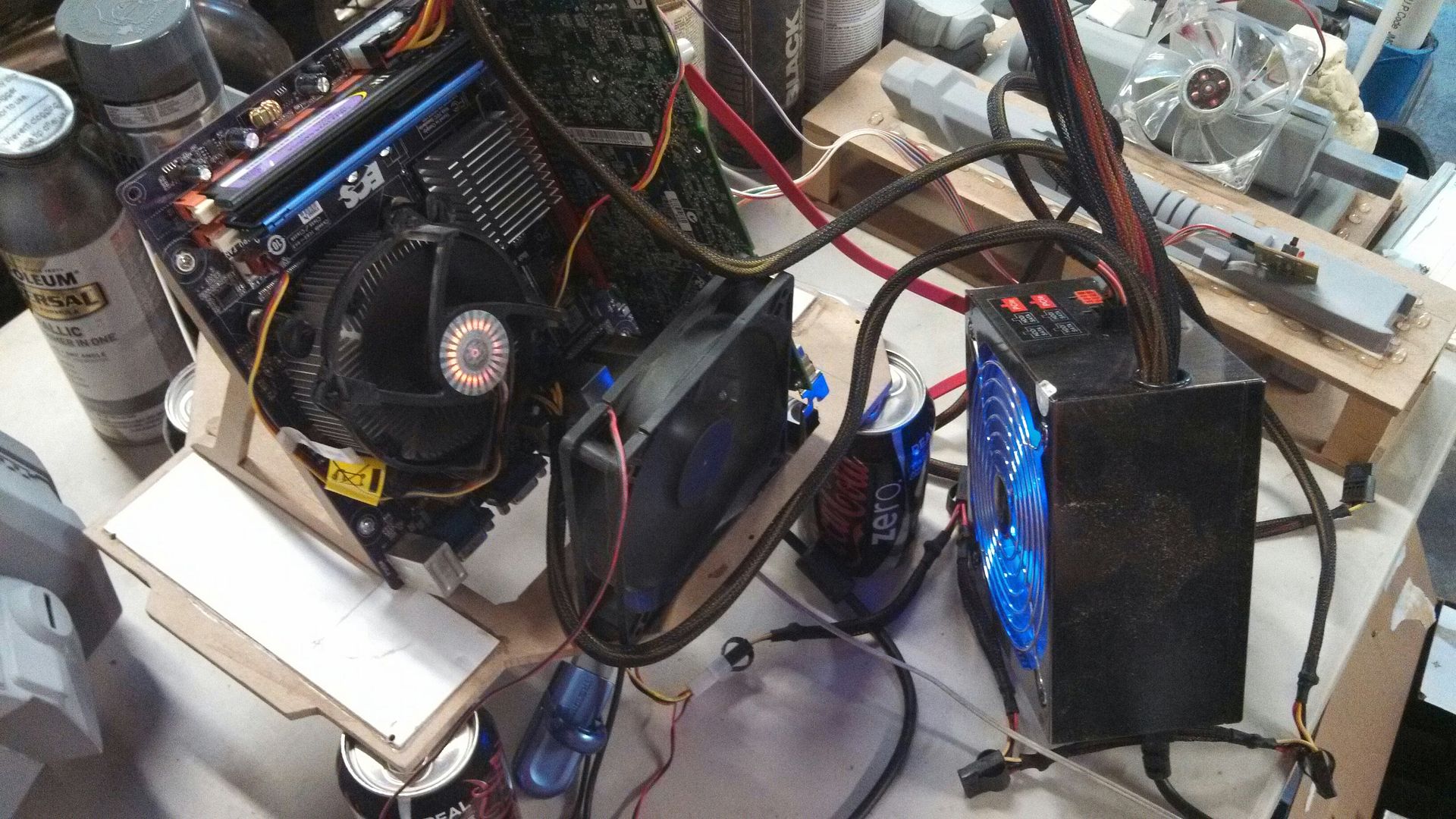
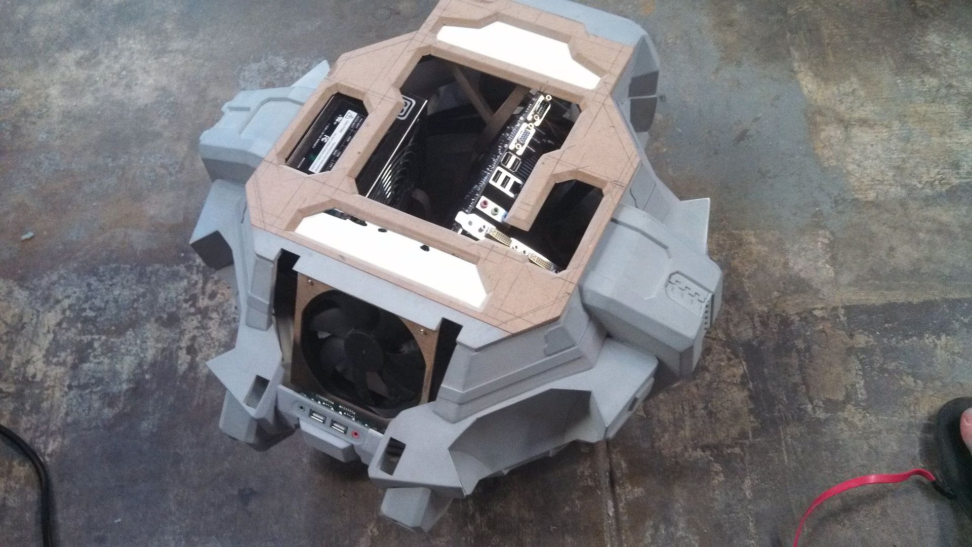
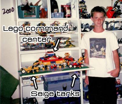
Fast forward a gazillion years later to 2010, and Starcraft II came out after Blizzard saying it would never happen! I immediately fell in love with the new command center, and in 2011 emailed an old high school friend who ended up at Blizzard doing 3D art for the games. I wanted a perfect reference to make this command center as accurate as possible. I also purchased a cheap, but somewhat capable desktop that I was going to integrate into the command center. Disclaimer: This isn't my first command center... errrr..... ......rodeo....whatever they say.
(I'm 12 here. And yes, I was the cool kid at skoo')
My request got lost in the ages.
I was on my own, and when I finally had the time/skills/money/resources I set out to do this , hopefully finishing around the second installment of Starcraft II, Heart of the Swarm. (March 2013) I had planned on a two month build. This was not made to be cast or sold, as many of my previous projects had been, this was "my baby". Possibly my longest anticipated project ever, to boot. So it had better be damn near perfect.
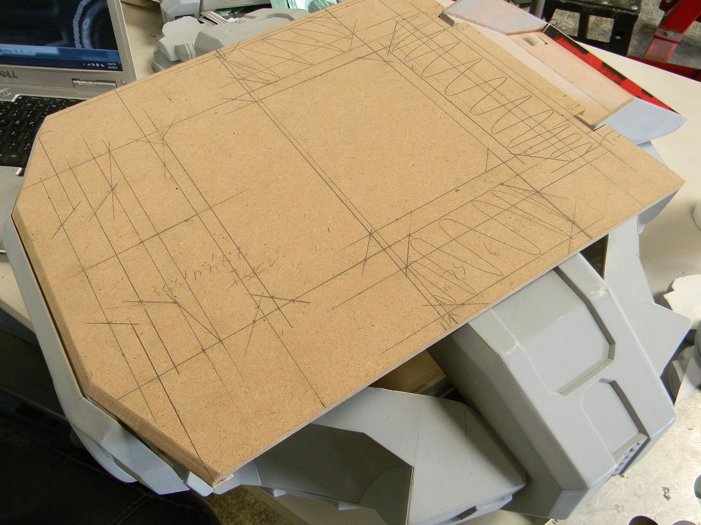
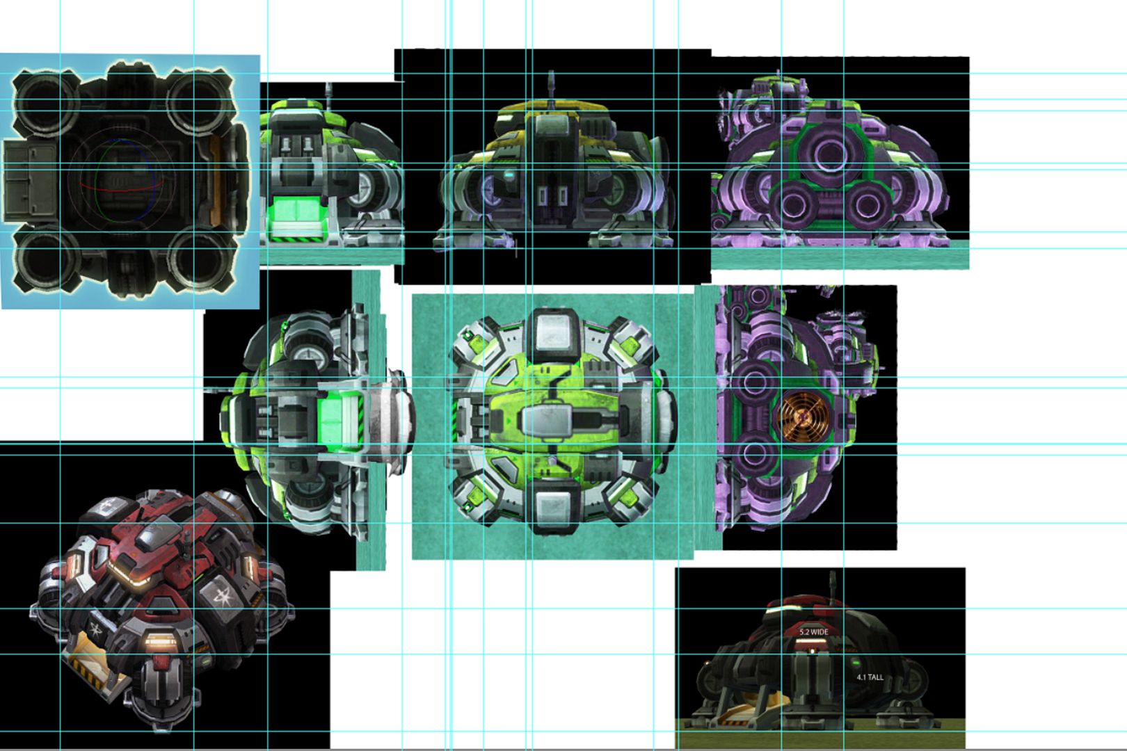
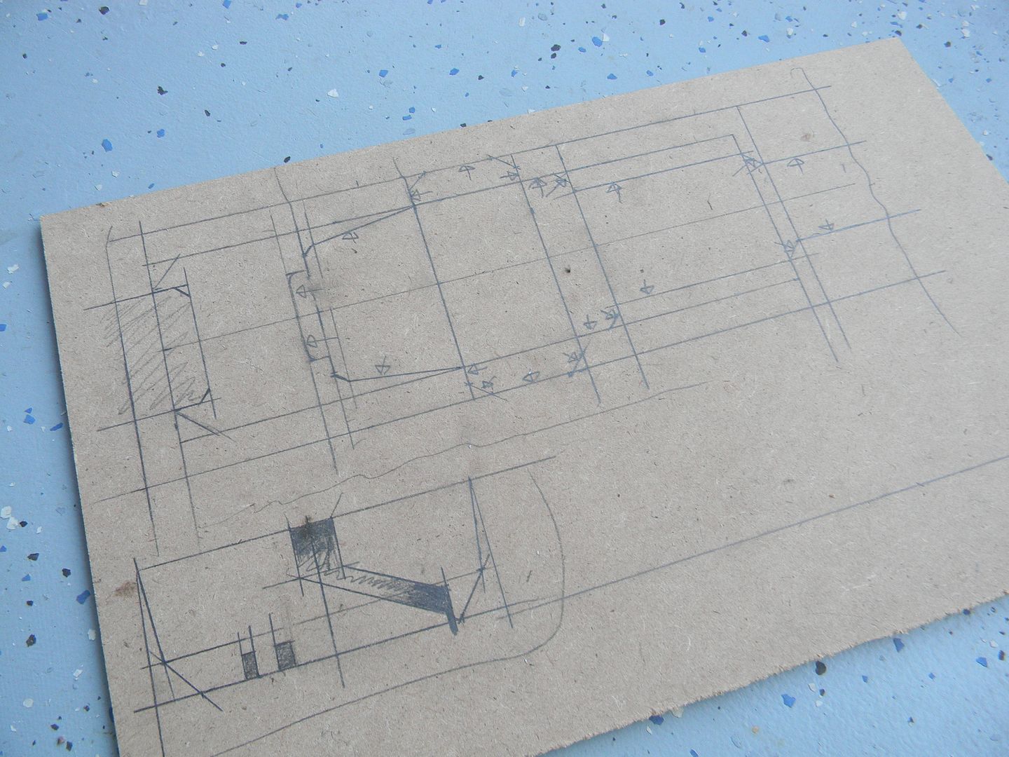
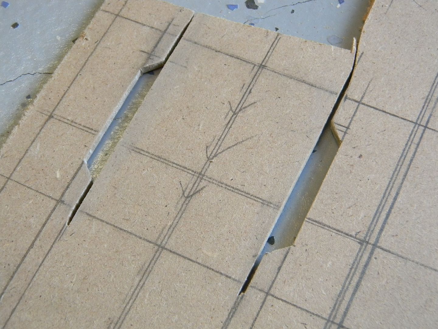
I made my blueprints, which are always screenshots. (I don't get this illustrator trend with blueprints!) The contour lines aren't hidden or anything in the screenshots.....Photoshop, scaling, and grid rulers FTW!
The problem here of course, is distortion. So, when I measured things I had to add or subtract 5-10% of the dimensions according to distortion to get things as accurate as possible. There's no formula for this, Just a lot of time in perspective/drawing class will help you scale things. I'm certainly not perfect, but its a start!
I won't drone you anymore with how I decided to scale the thing. But since it wasn't a 1:1 prop, there was no "accurate" size it needed to be. Just large enough to fit all (or the most essential) computer components I wanted inside it. I decided on roughly a 22" x 22" footprint.
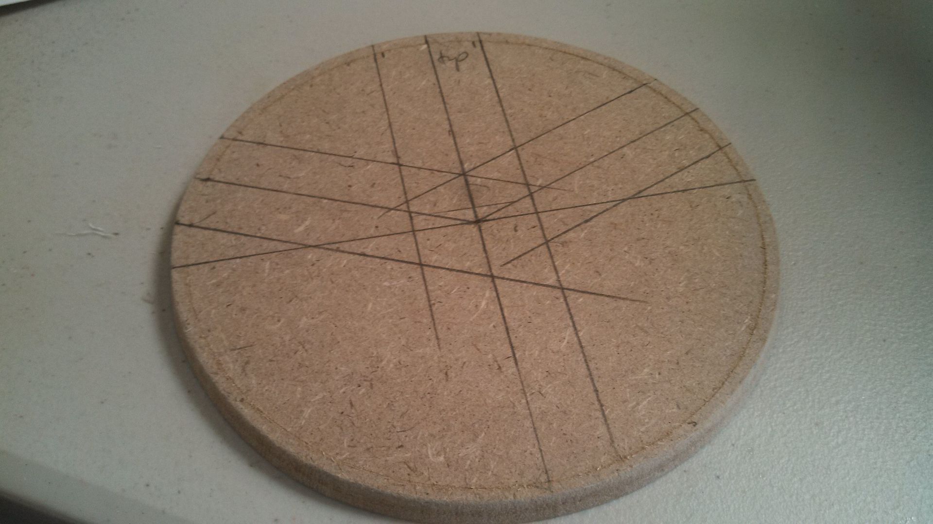
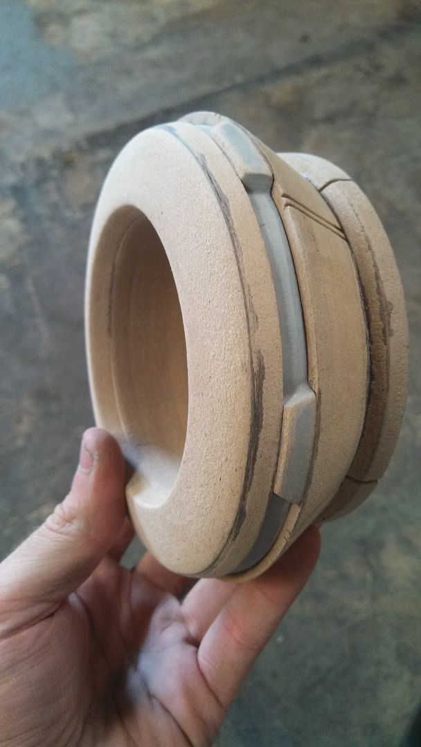
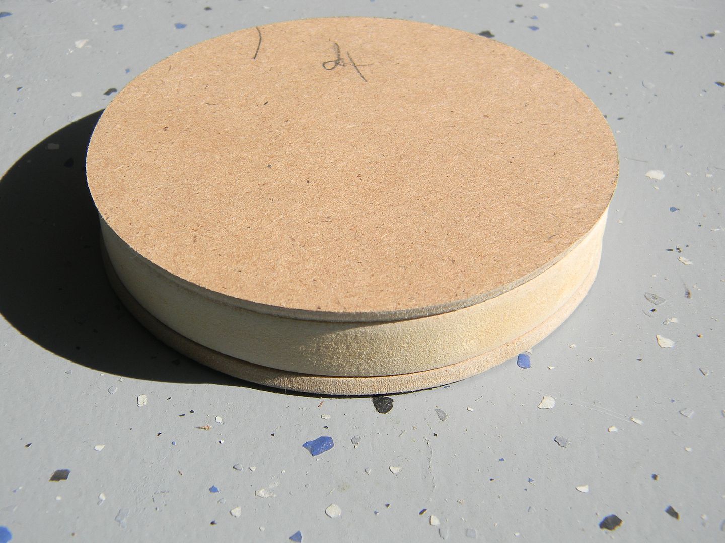
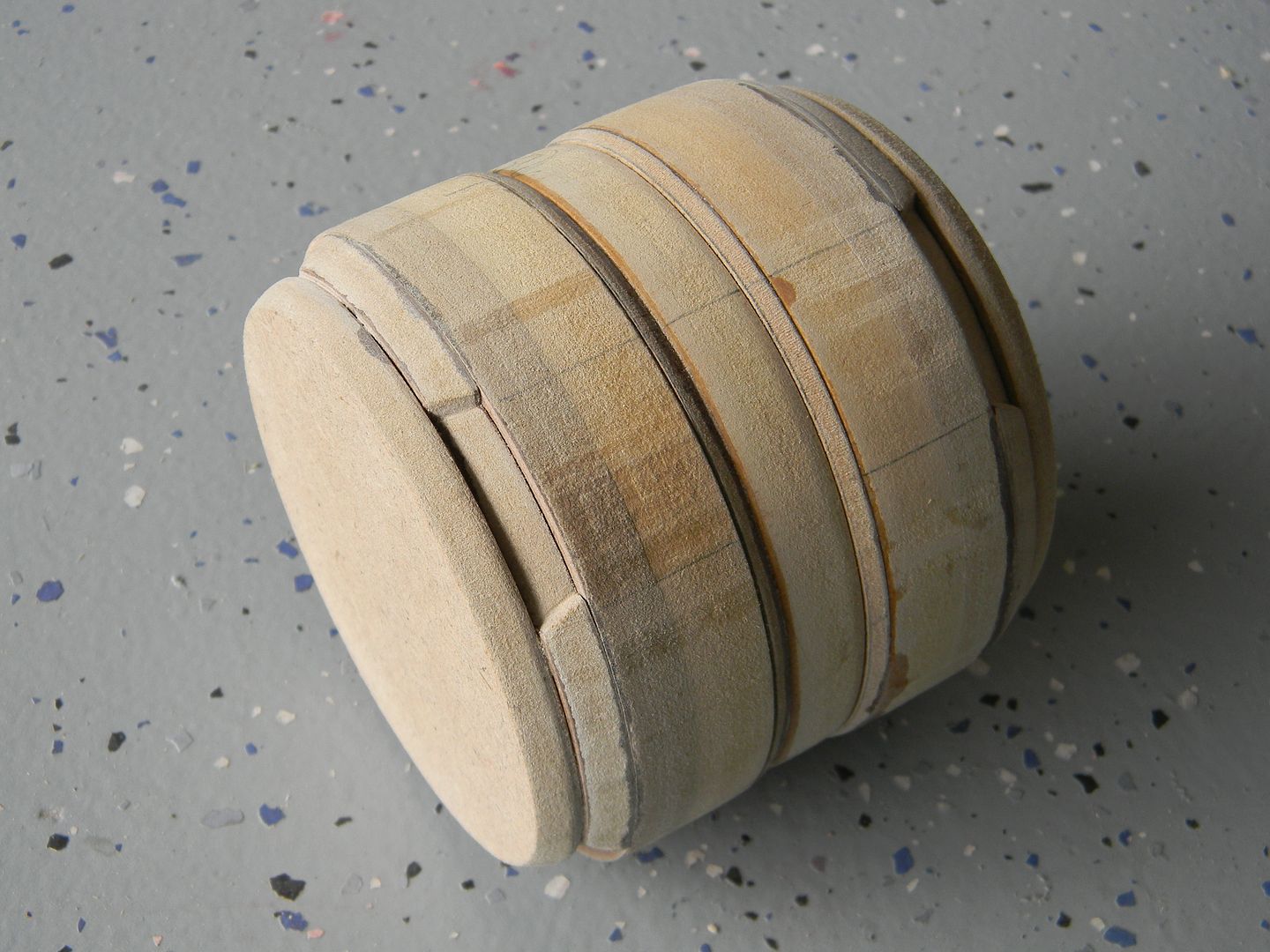
Since the knee joint is circular, I decided to tackle it first. Also, by being circular I could align all of the views in relation to the width of the knee joint, and should be the same width at any view. Not owning a lathe or having access to one meant that it was going to be a pain, and I wanted to get it over with.
Materials: (up until casting) Styene. MDF. Not a drop of anything else.
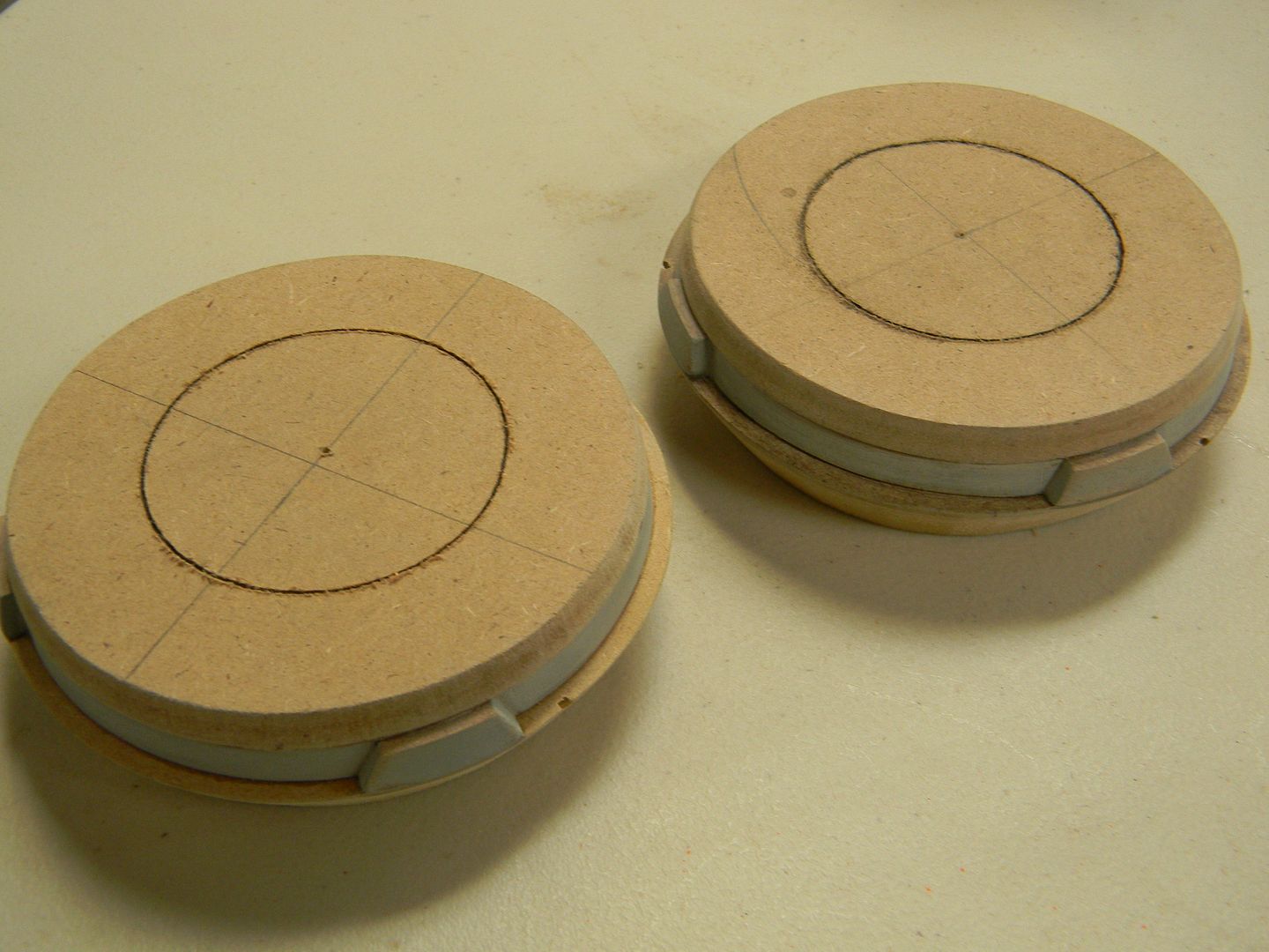
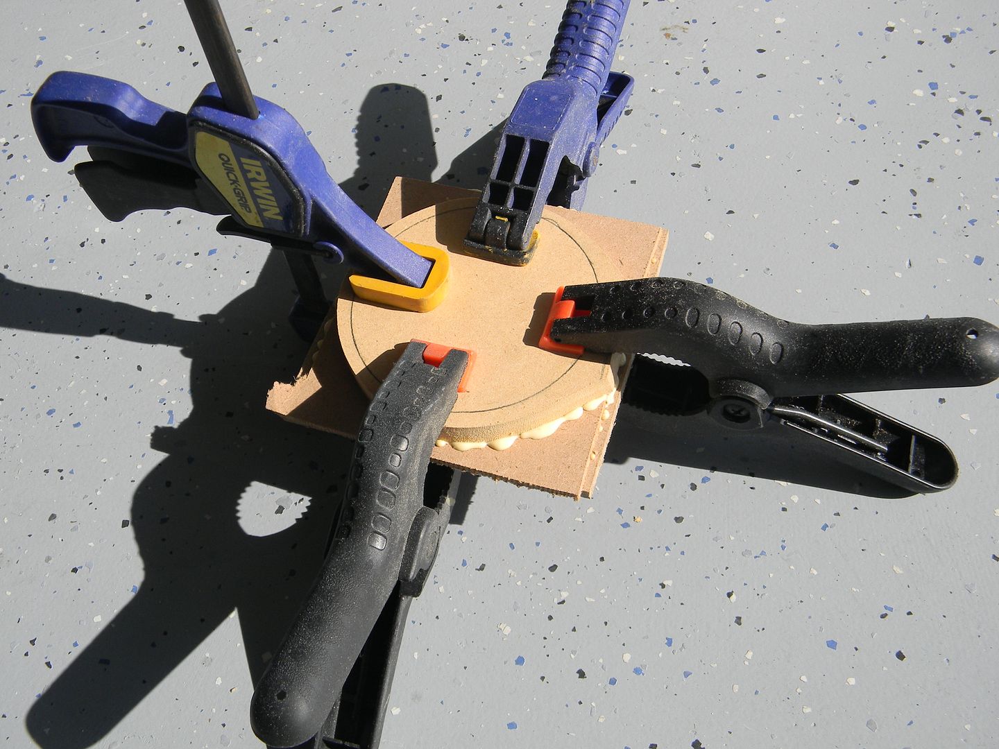
I figured the channel in the middle of the knee was a good place to start, along with the 1/8th inch beveled bits that transition into the wider parts of the knee. (all MDF was cut on a scroll saw. No routers, no guides, ain't nobody got time for that. Word of advice though, don't try to cut a perfect circle as your first cut.
knee channel
It gets old, but when you cant find a certain thickness of something, you have to laminate other thicknesses and do it yourself. Sometimes I coat the surfaces in varying thicknesses of styrene to get a really accurate thickness. These are laminated together and cut as one. Cutting two circles separately and then laminating them can be tricky.
laminating materials
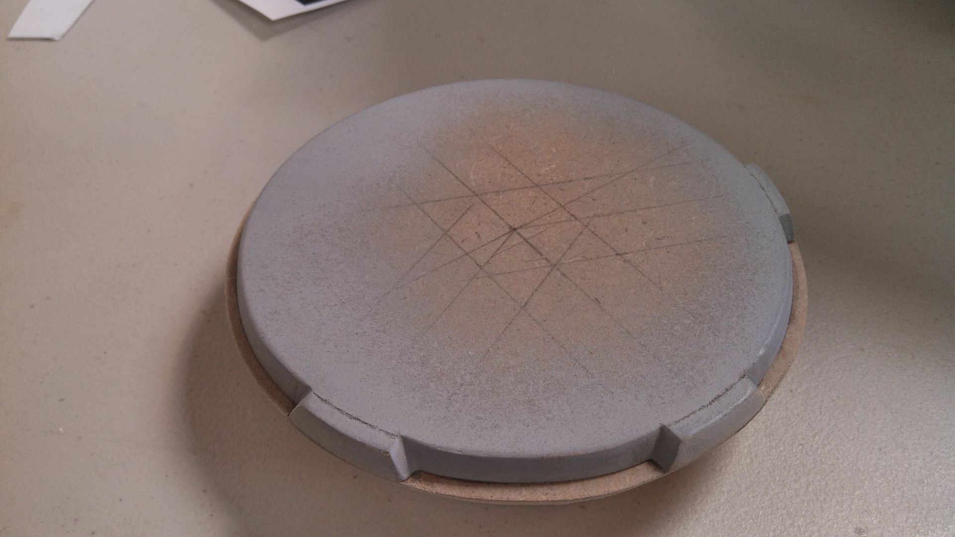
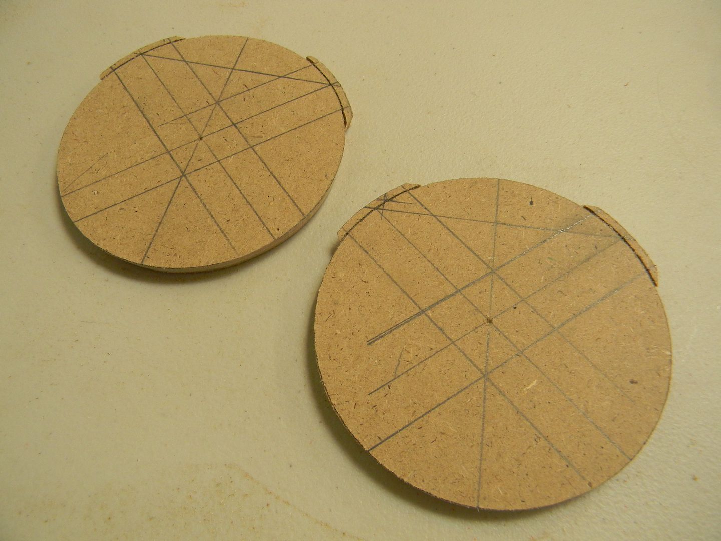
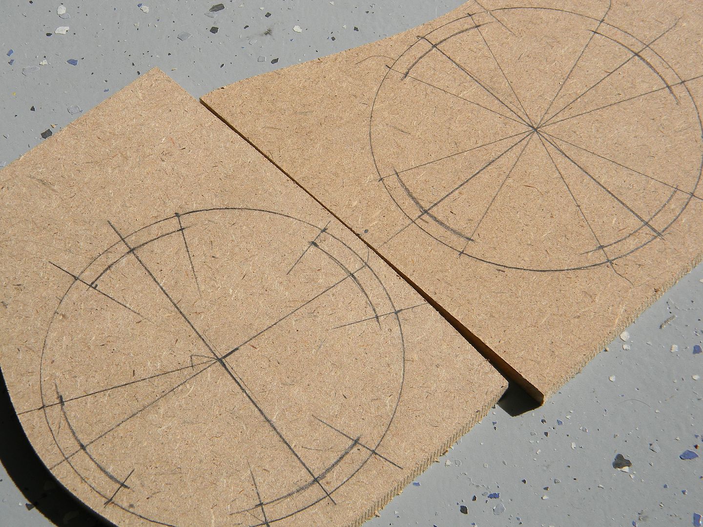
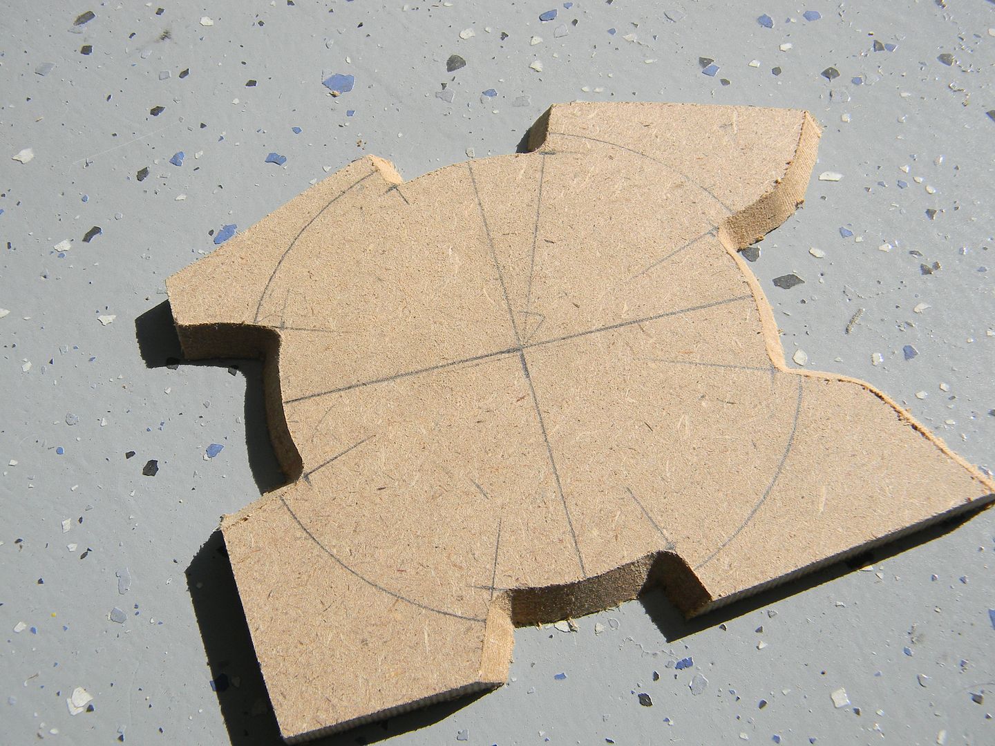
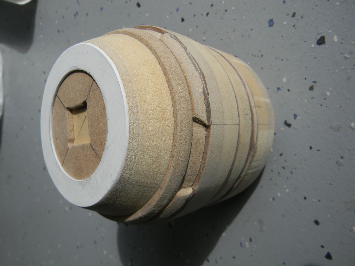
After the thicker circles were cut, the ends of the cylinder start to taper -and- have 4 tapered notches spread out evenly. Using dem maths, I drafted out the notches and cut them at the same bevel as the outside of the circle. I used an exacto and a small detail file to clean them up.
Dem geometry classes come in handy!
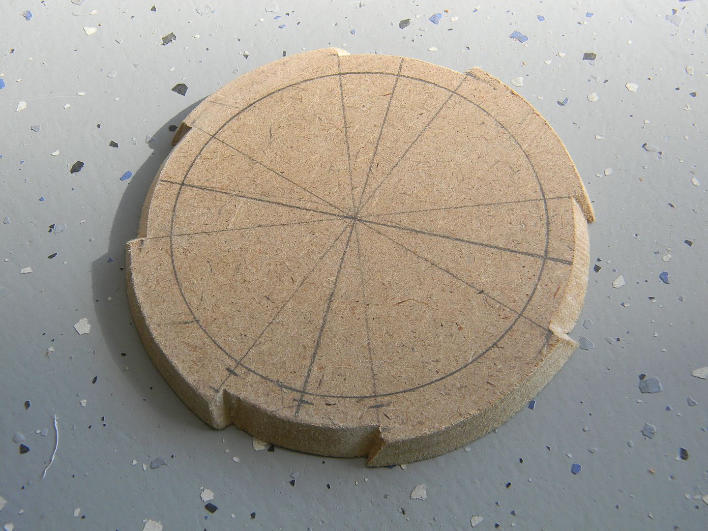
Purdy.
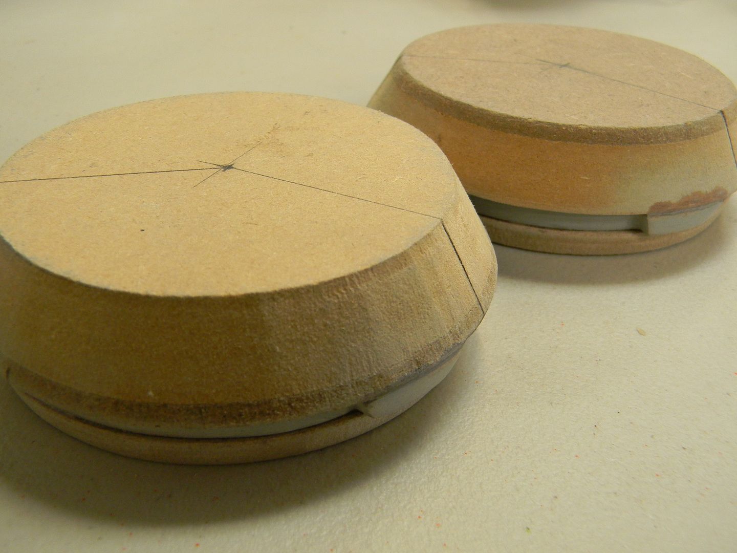
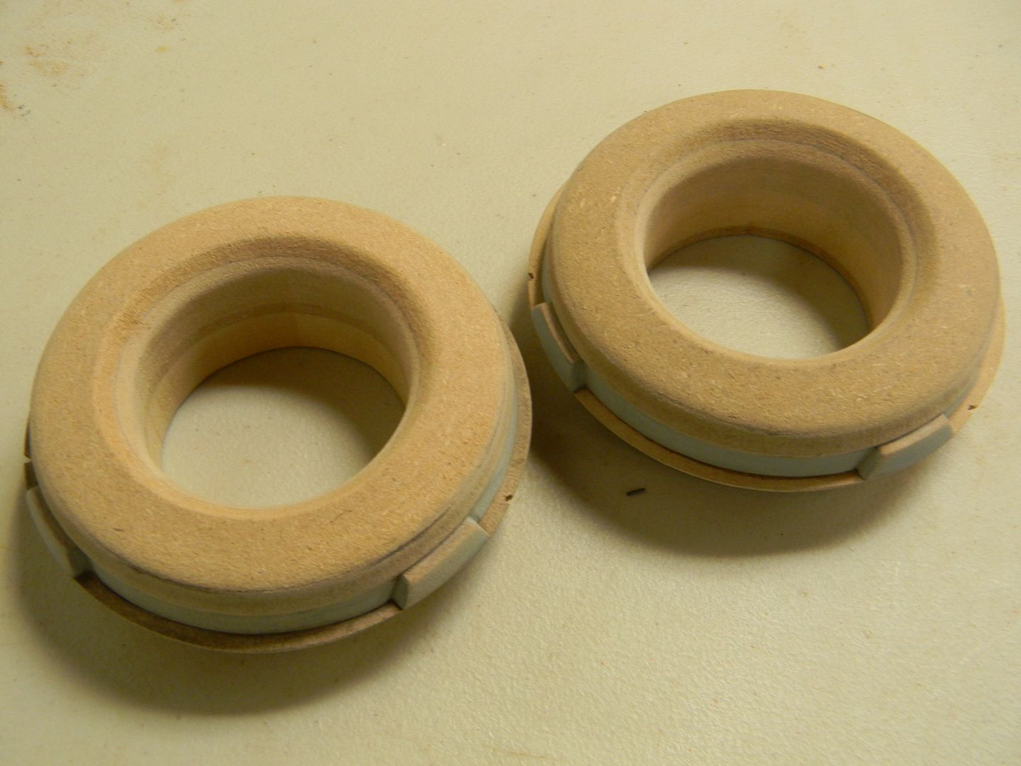
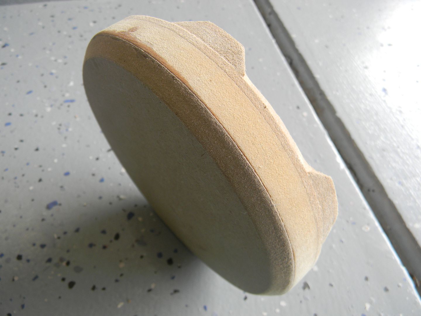
I made two of them, and then glued them to the aforementioned "thicker circles"
Stack o' MDF
The next layer of beveled circles are just a hair smaller in diameter than the ones with the notches.

foot assembly blocked out
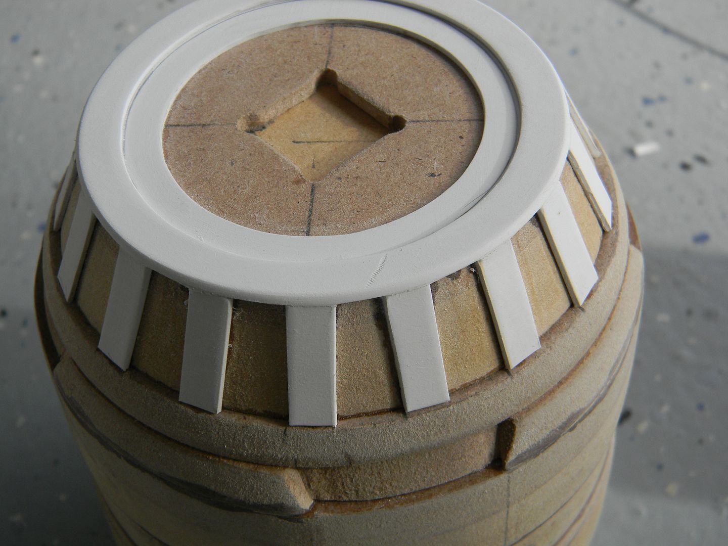
Here's an example of putting a few of the previous steps together. The "endcaps" were made by cutting the circular ring out of styrene, then laminated to the square detail piece made from 1/8th" MDF, then laminated to a thicker scrap of MDF, and then beveled at the same angle but smaller diameter as the previous beveled circle. So that makes 3 steps of beveled circles on each side, for a total of 6. They had to be near perfect too, the human eye can see defects in circles very very easily.
Some of these parts can not be done on a lathe.
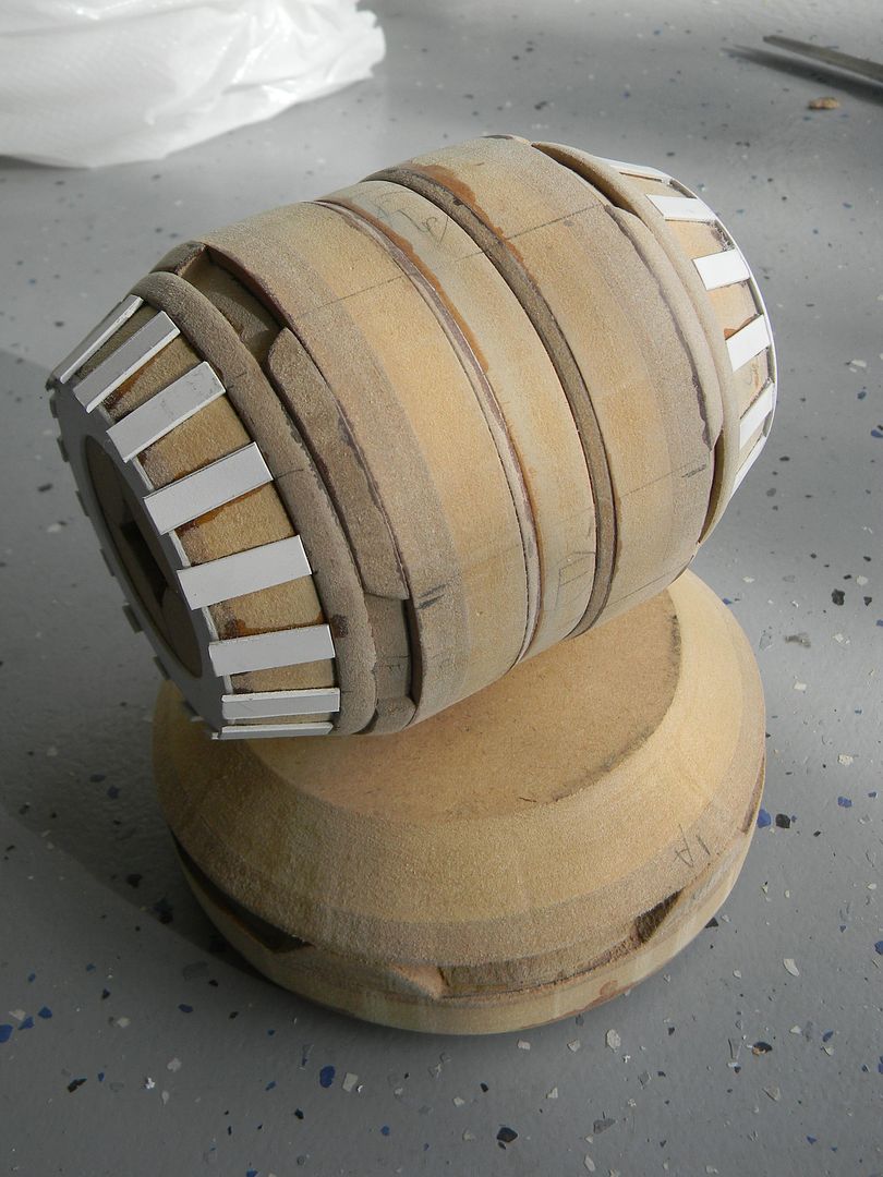
I putt off the next step for a good 15 minutes. I was not looking forward to cutting bits out of a sheet of styrene and manually spacing them at the correct angles around a circle. Now, you may be asking "Not all of the knee shows. Its about 1/3rd hidden. Why are you detailing the whole thing?" Because this part was going to be the master for a cast, I figured having the thing detailed all the way around would allow me to hide the most bubbled sections of the cast, and use the better parts of the cast as the parts that show. If I only detailed 2/3rds of it, I would have no options.
Funnn!
I use super glue and styrene dust as bondo for small cracks. Finished up the strips and sanded/filled the little imperfections.
The dark spots are dried/sanded super glue.
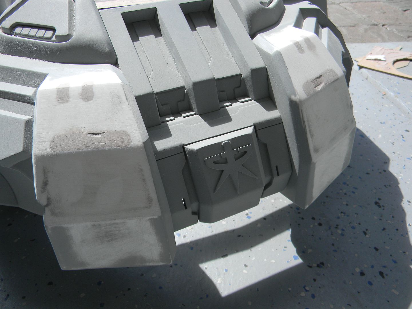
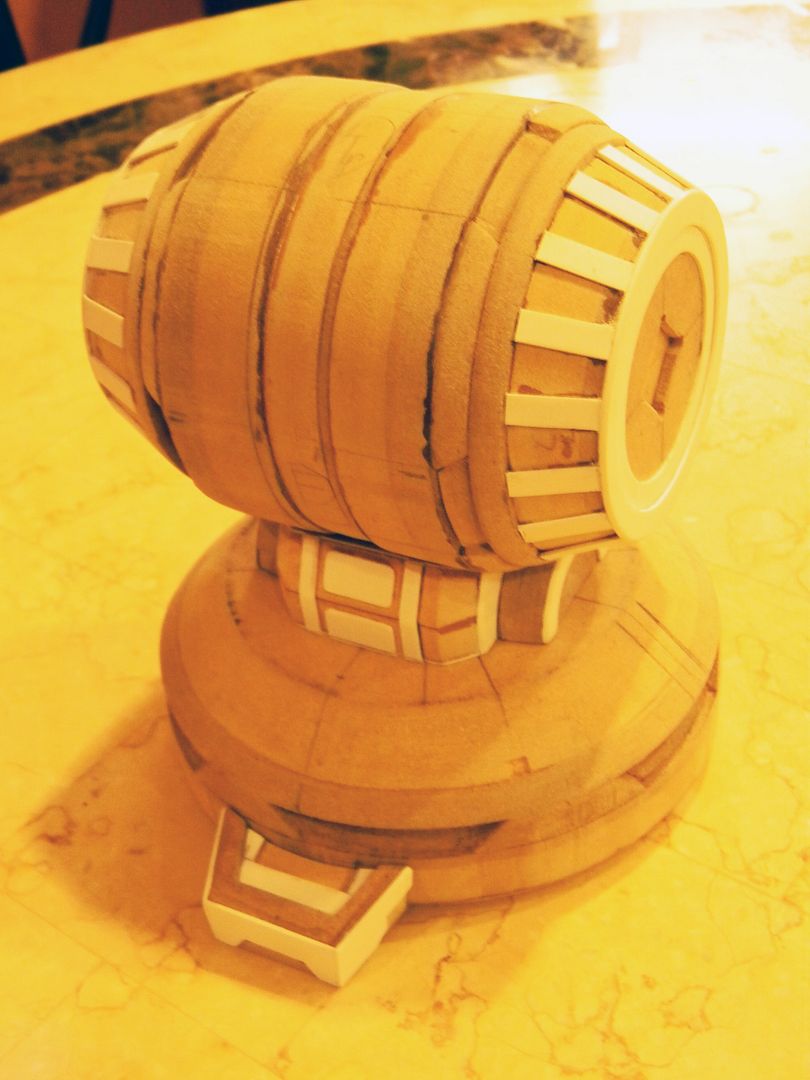
Using nearly the same process as the knee, I blocked out the notches in the foot.
This ended up being a waste of time. More on that later.
 End of day 1.
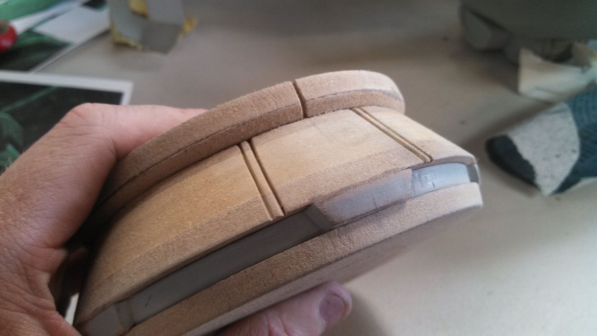
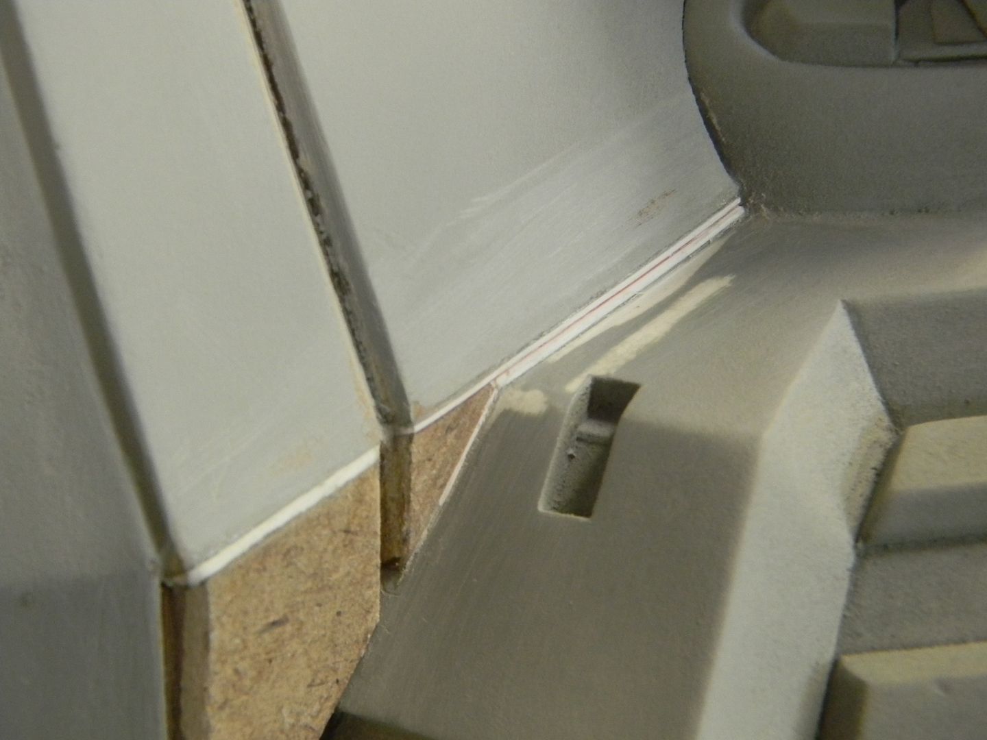
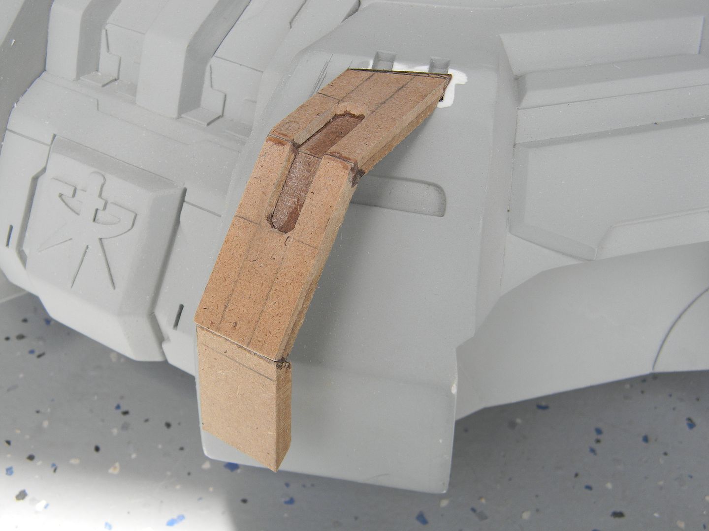
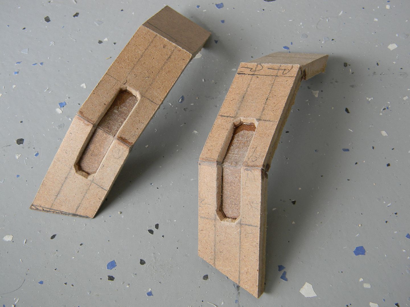
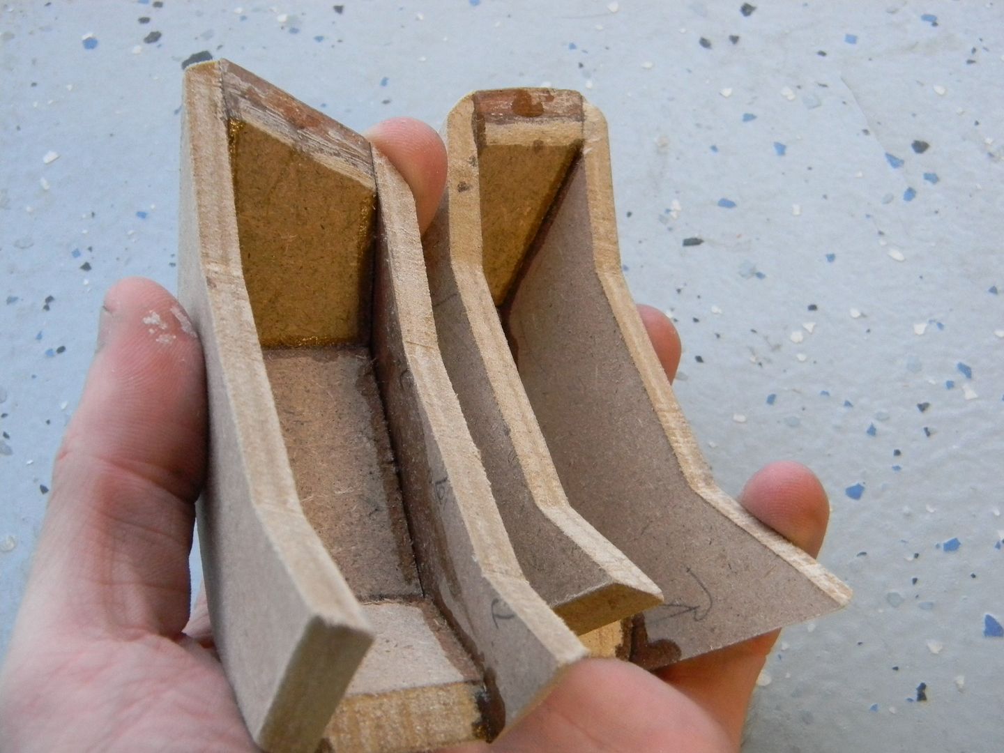
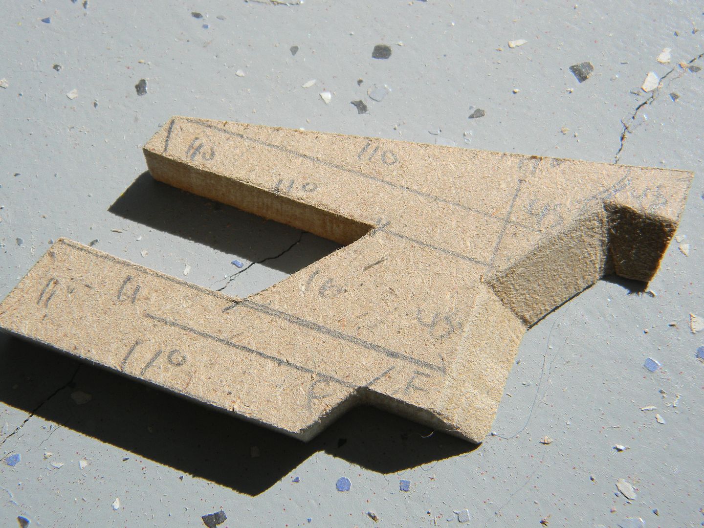
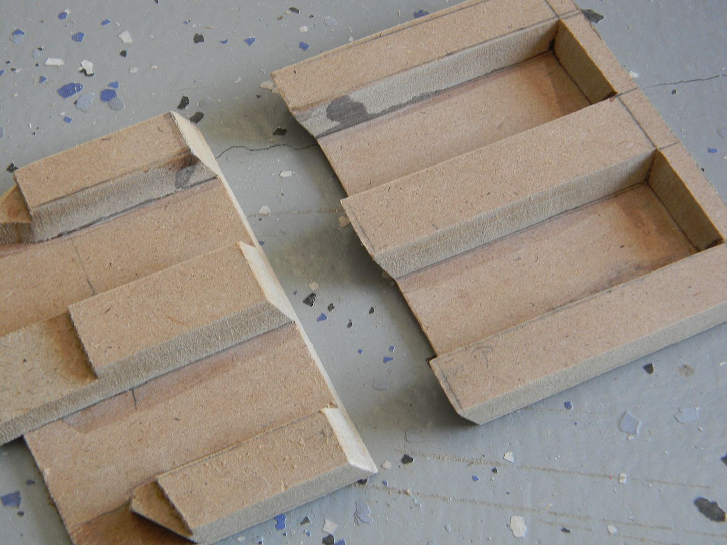
The Photos are a bit lacking for the rest of the foot, but you can see here I simply made a curved cut out of a 1/2 inch piece of MDF at a 13 degree bevel or so, then cut the "ridge" out of 1/8th inch MDF and did the smaller details with styrene for the toe.
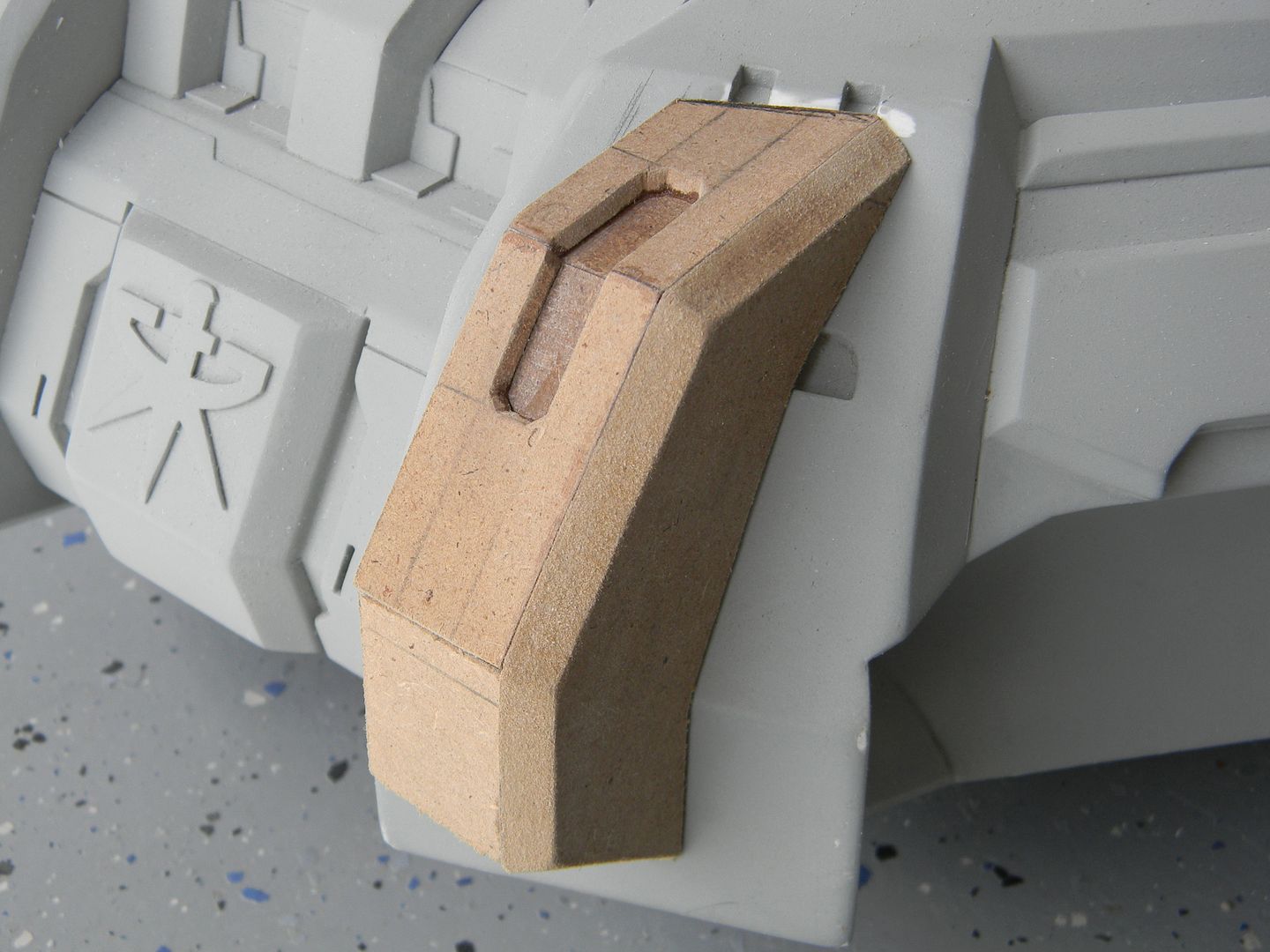
I started the drafting for the small details and panel lines as well. I used the intersection of the lighter and darker MDF as a guide for one of the panel lines. They were scribed with an exacto knife, then sanded out with a folded piece of 220 grit sandpaper.
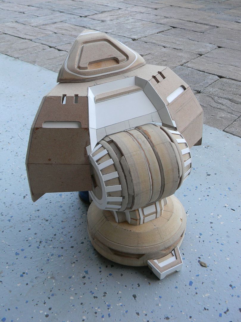
Once I saw the size of the nearly completed foot, I realized what I was getting into.
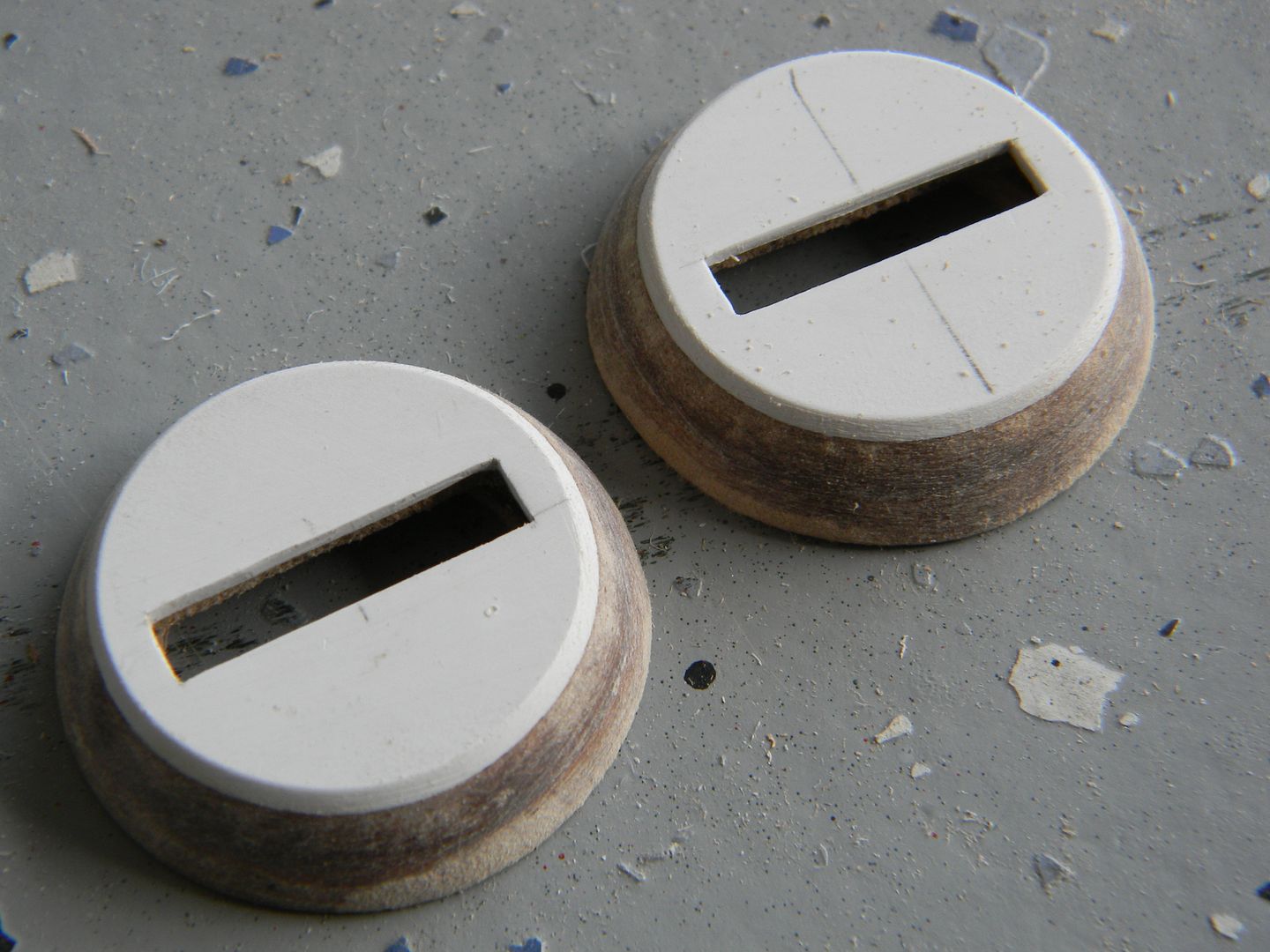
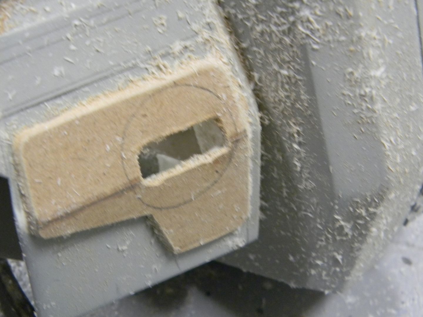
The inner styrene circle is the diameter of a coke can.
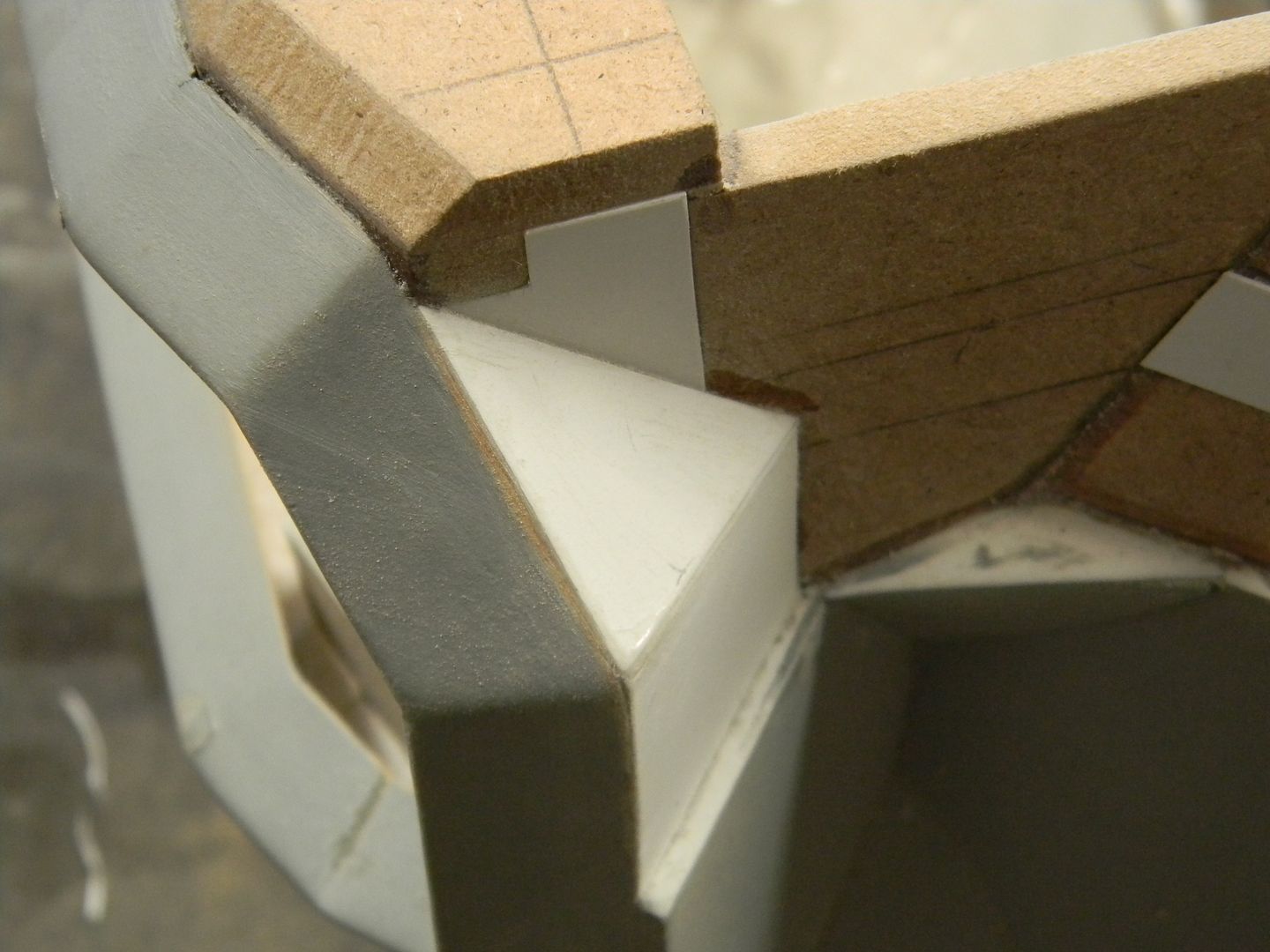
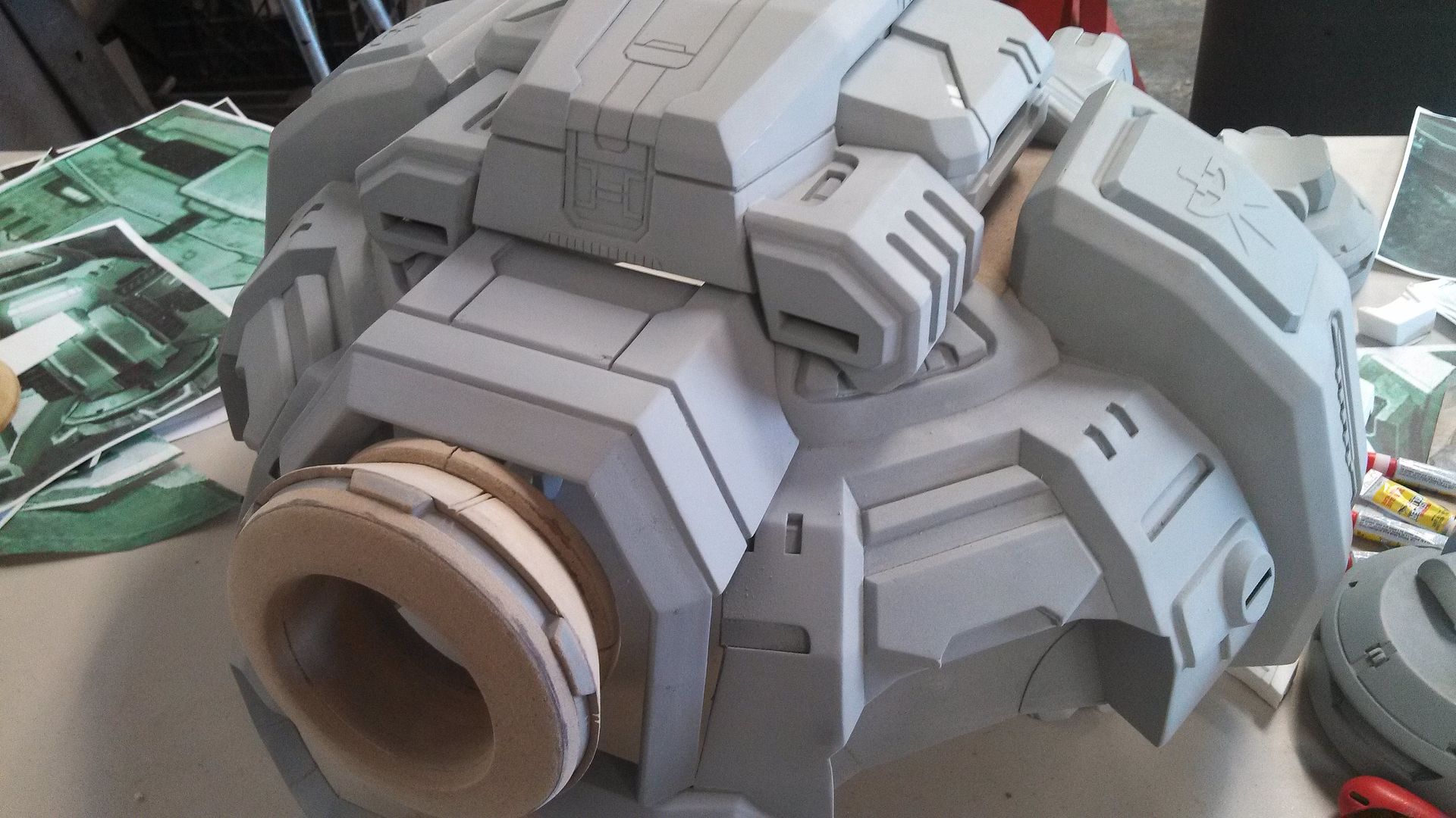
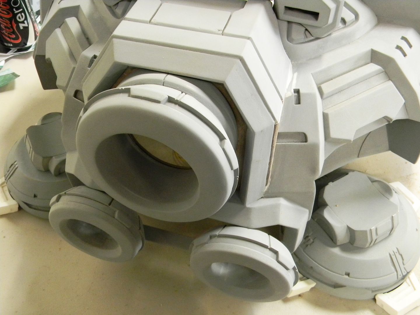
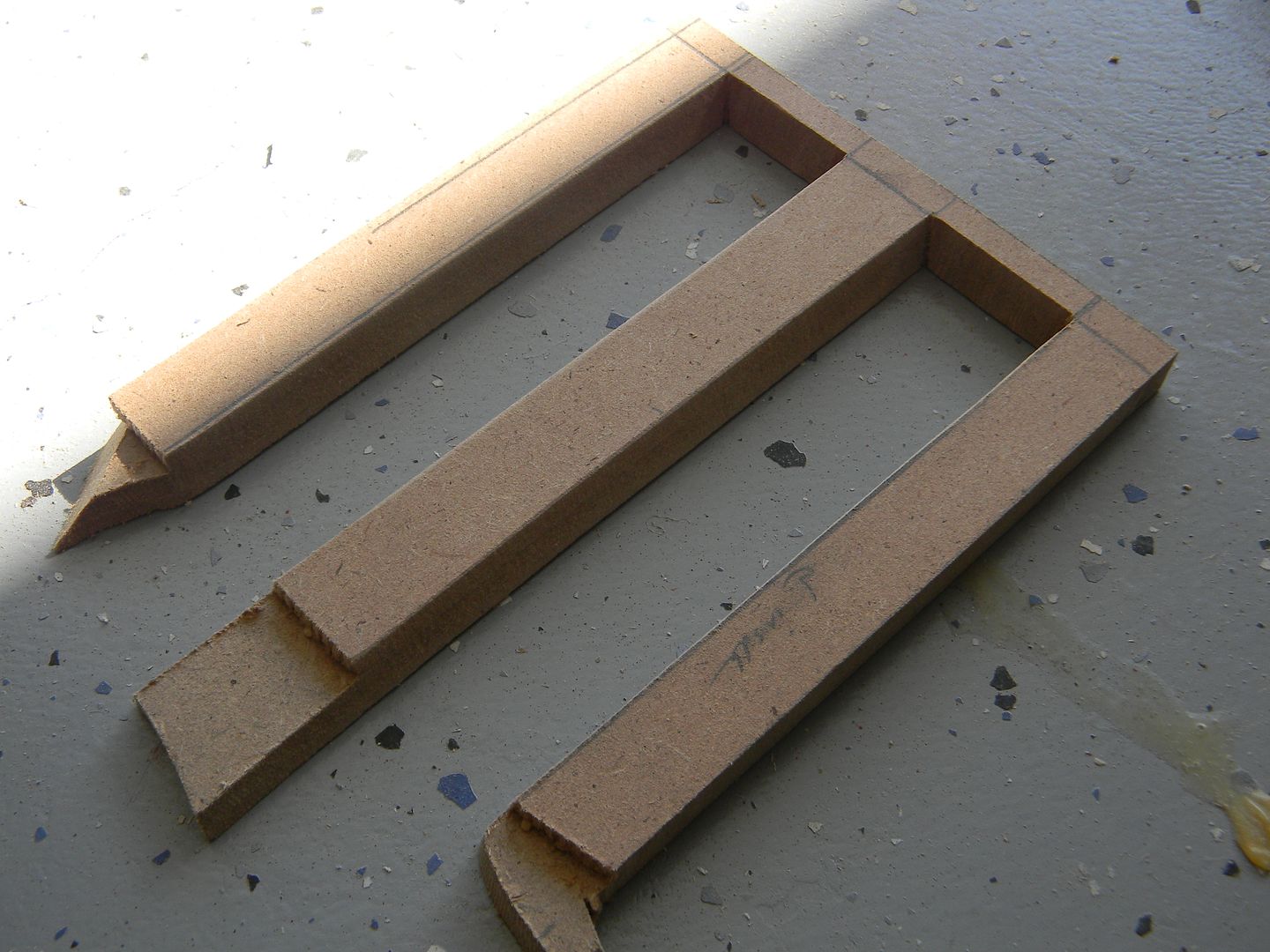
With the scale set in place and a nice physical reference of the knee, I could start the "shrouds" that surround it. I used the top view of the reference to cut the first piece. It got a but tricky from there. Without a "straight on" shot of the panels, it took many many views to measure out the 4 angles this piece breaks up into.
I usually use 1/4" for structure, but this piece was going to be cast and 1/8th is easy to cut/sand/glue.
It helps to draft a visualization and test fit the angle before actually cutting it.
This part was a bit tricky. I had to hope that the part was the correct width, angle, etc so that when I cut out the intersection for the knee joint, it matched the reference and didn't sit too high or low. It ended up sitting a but high, so I later moved it down and filled the gap with styrene.

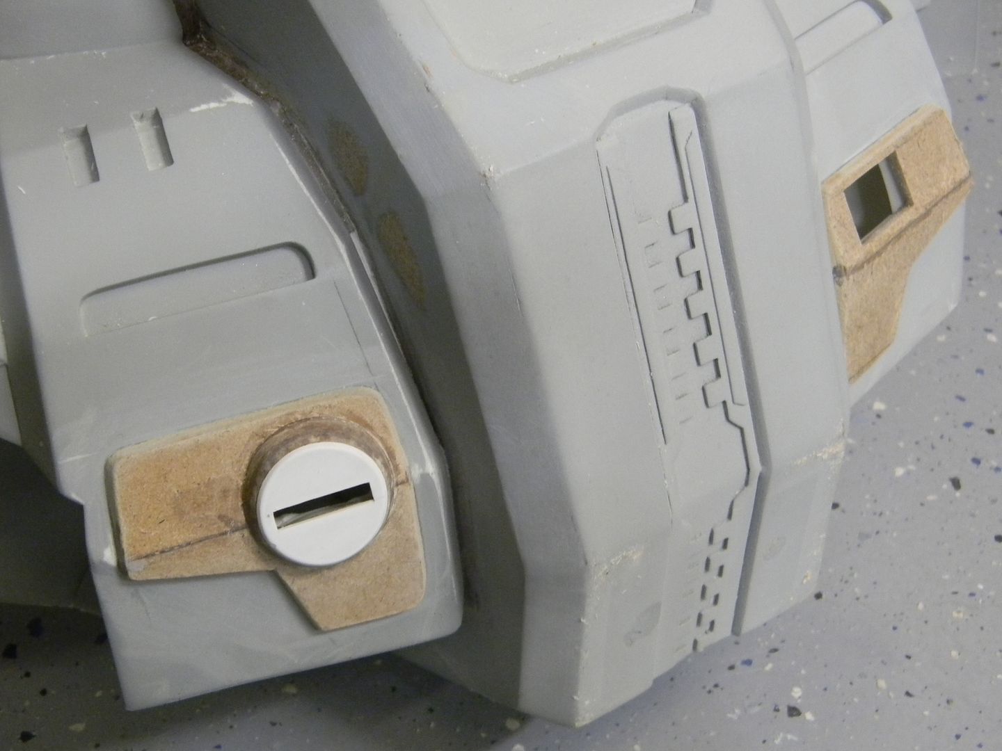
The knee really does dwarf a coke can.
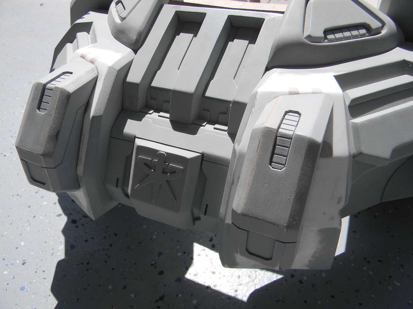
The next part was a little "hat" that sits above the shroud. these had to be perfect, as they get "projected" and copied 4 times around the command center. If they were even a degree off in any of the angles, It would show since they all sit at 4 evenly spaced and opposite facing orientations. I started with the beveled details, measured out some triangles, and dremeled/sanded away. I made an angled cut at the bottom that was a bit tricky to measure.
Styrene was used to give the part a little more thickness/depth.
The styrene ended up being a huge help in keeping track of the angles.
You can easily tell the sanding is not straight in this stage because of the wonky styrene line.
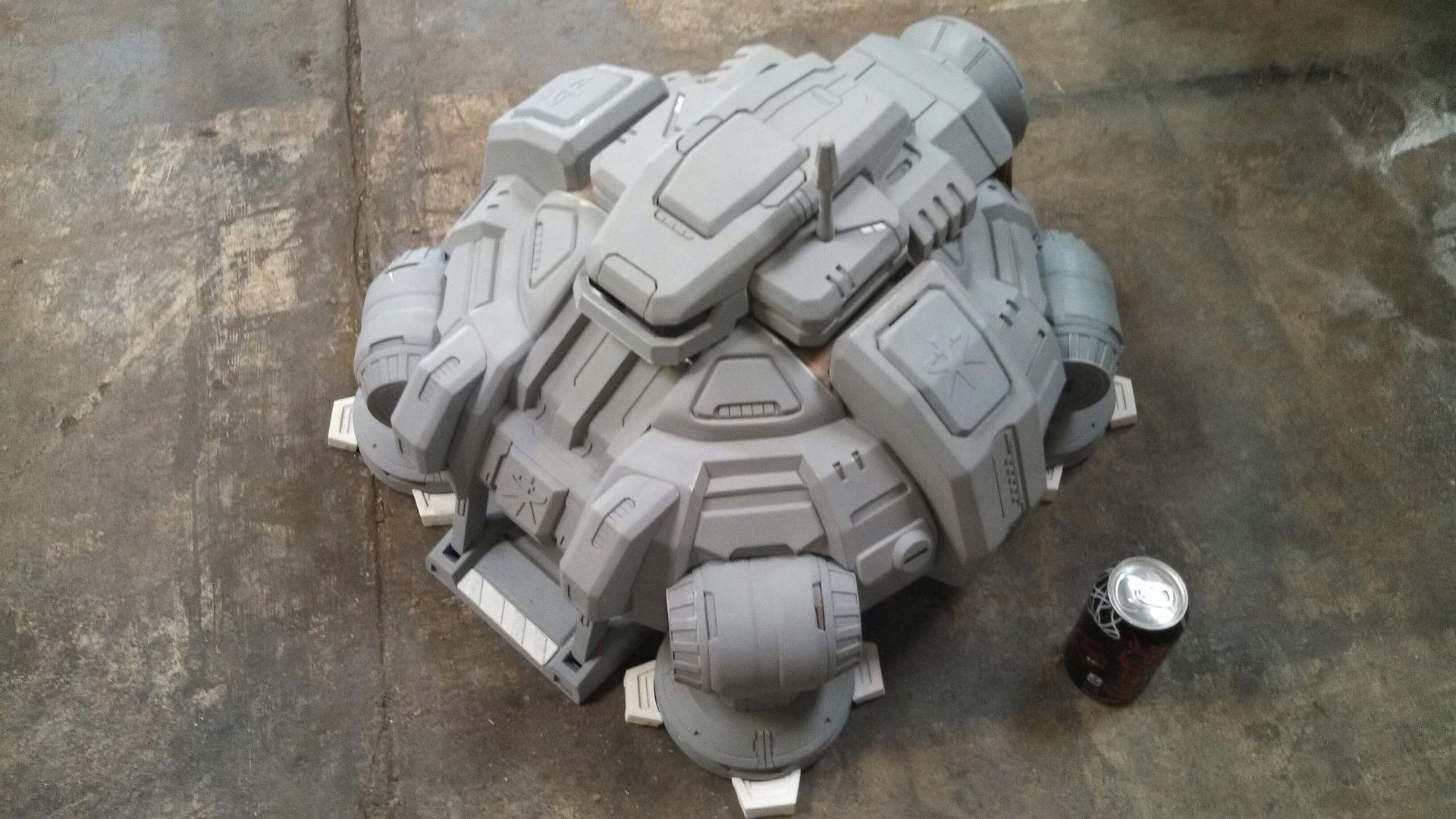
Some styrene, sanding, and time in front of the TV left me with this by the end of the day.
At this point I felt like I was roughly a quarter done. I knew I wasn't, but that's
what it felt like!
By this point, I was pretty sick of looking at these parts and decided to detail them between other stages. If you pay attention to the "test fit" pictures of this in the following posts, you can see bits of detail added here and there.
With me (and a lot of makers) I have a habit of not finishing something 100% before moving onto the next stage.
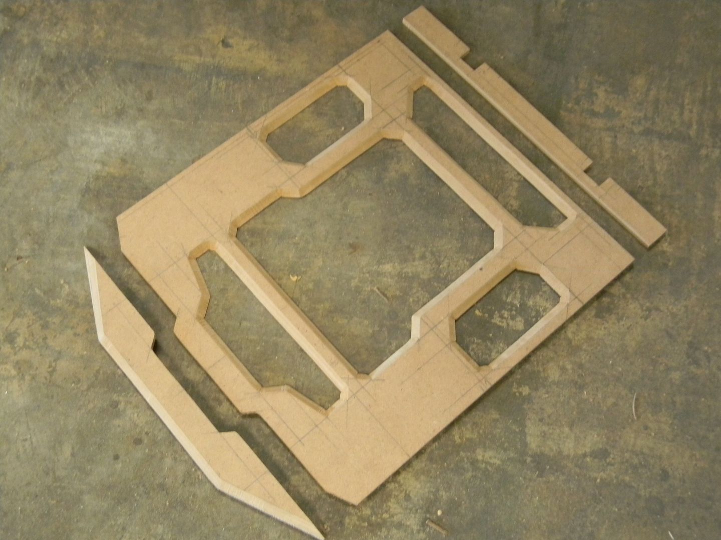
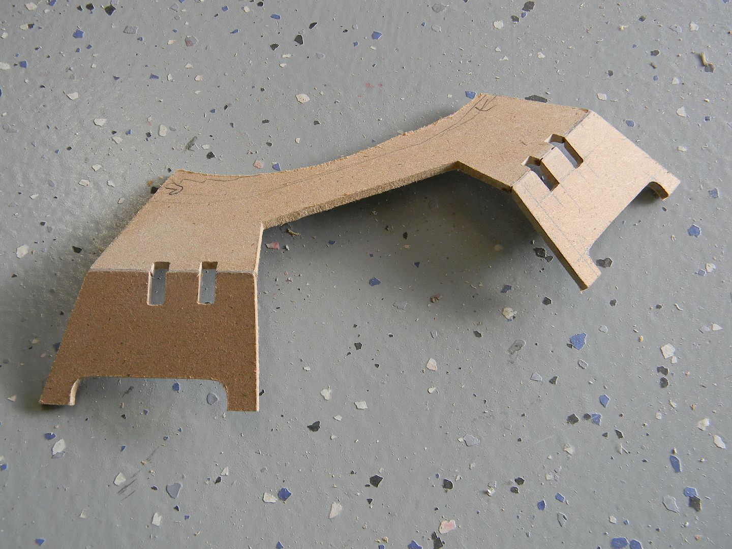
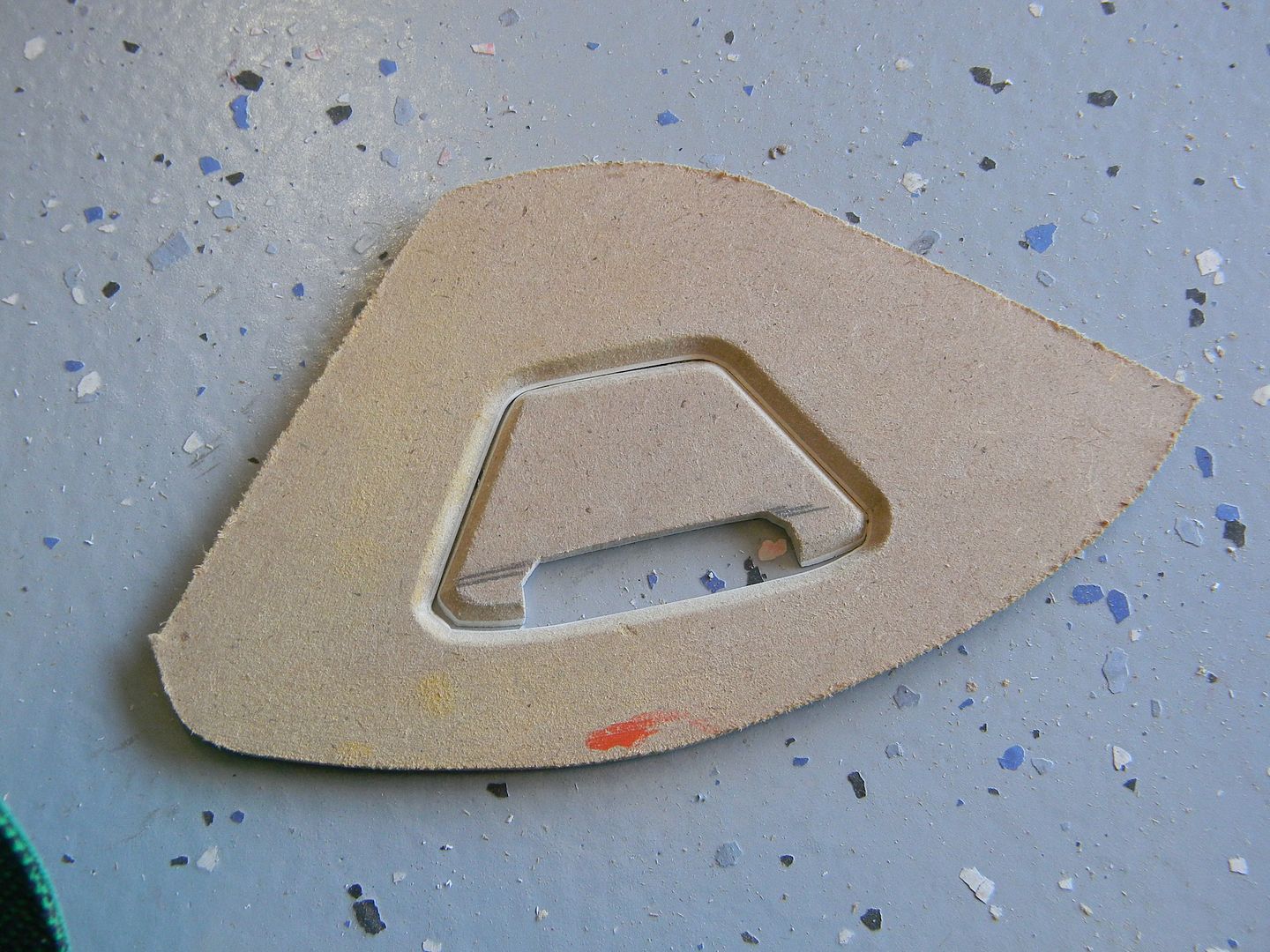
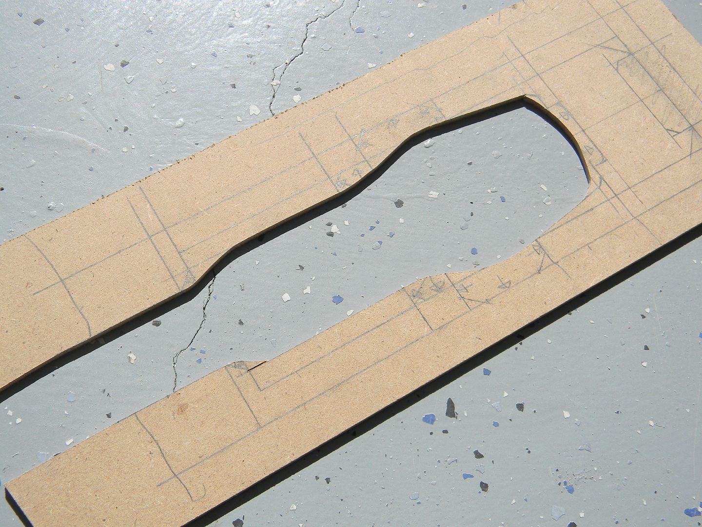
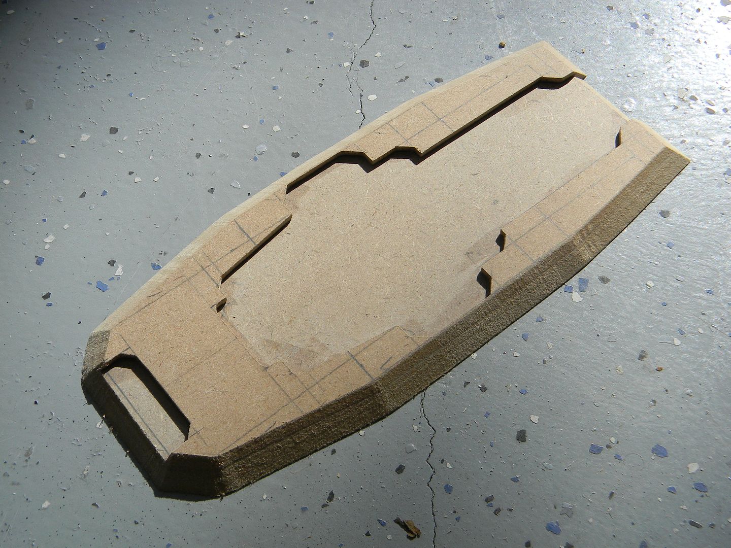
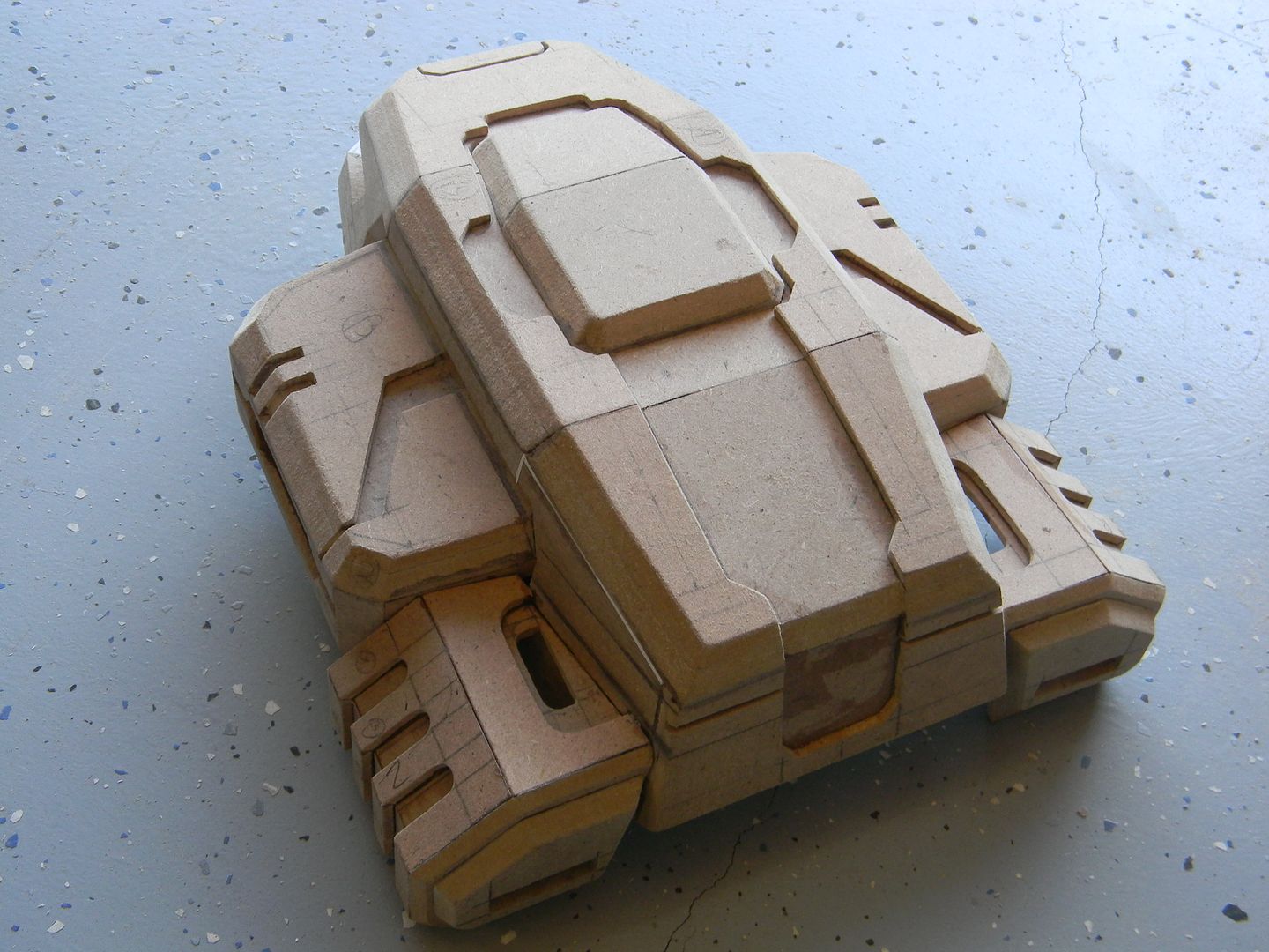
With that said, I made no effort to break the habit and started on the command module. This was the most tricky part to scale, as the distortion was the heaviest out of all of the parts in the references. I just did my best and started drafting.
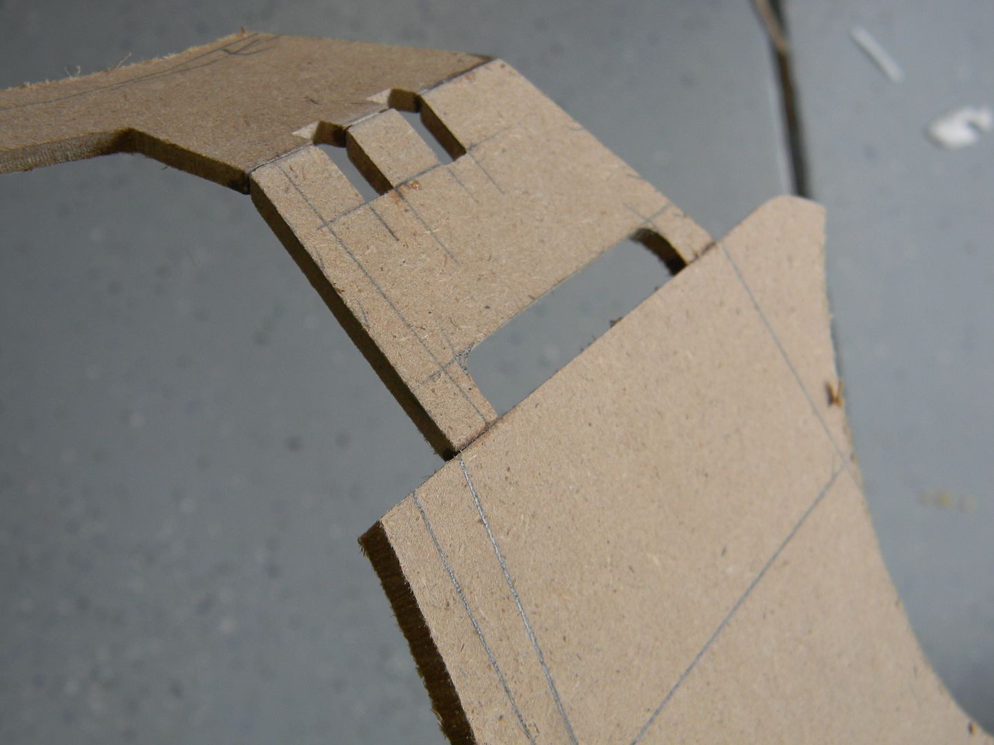
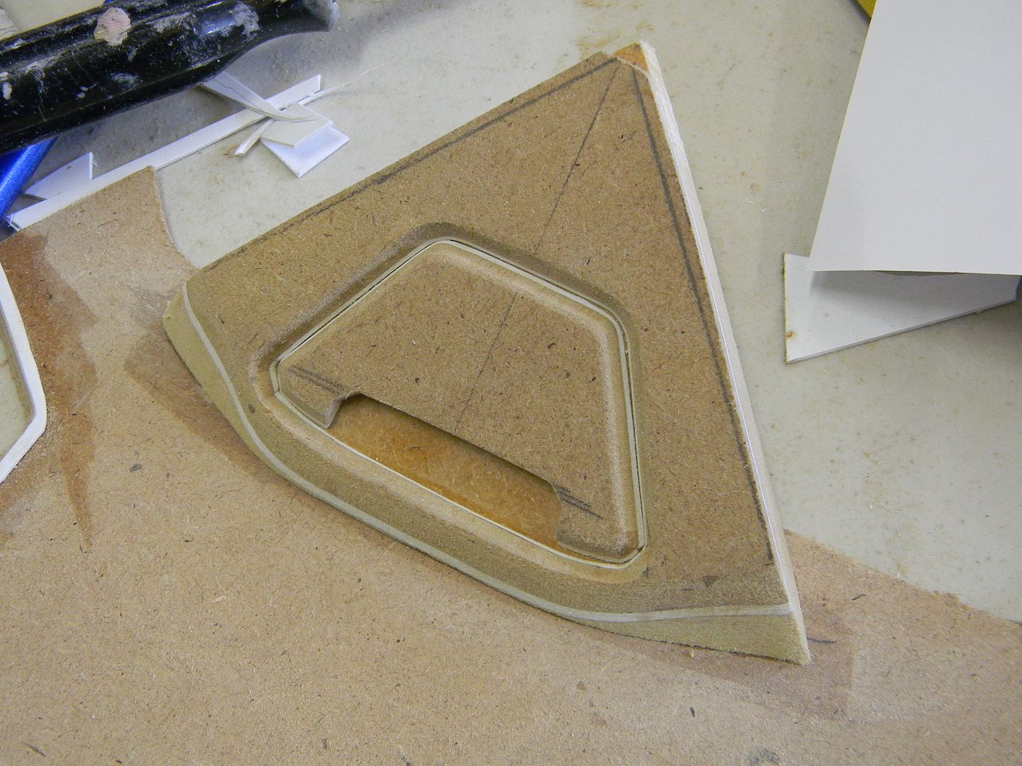
I could have printed out a template to trace, but it would have the distortions mentioned. I just went old school and drafted out the top of the command module as well as the little "ears" on the sides, accounting for distortion.
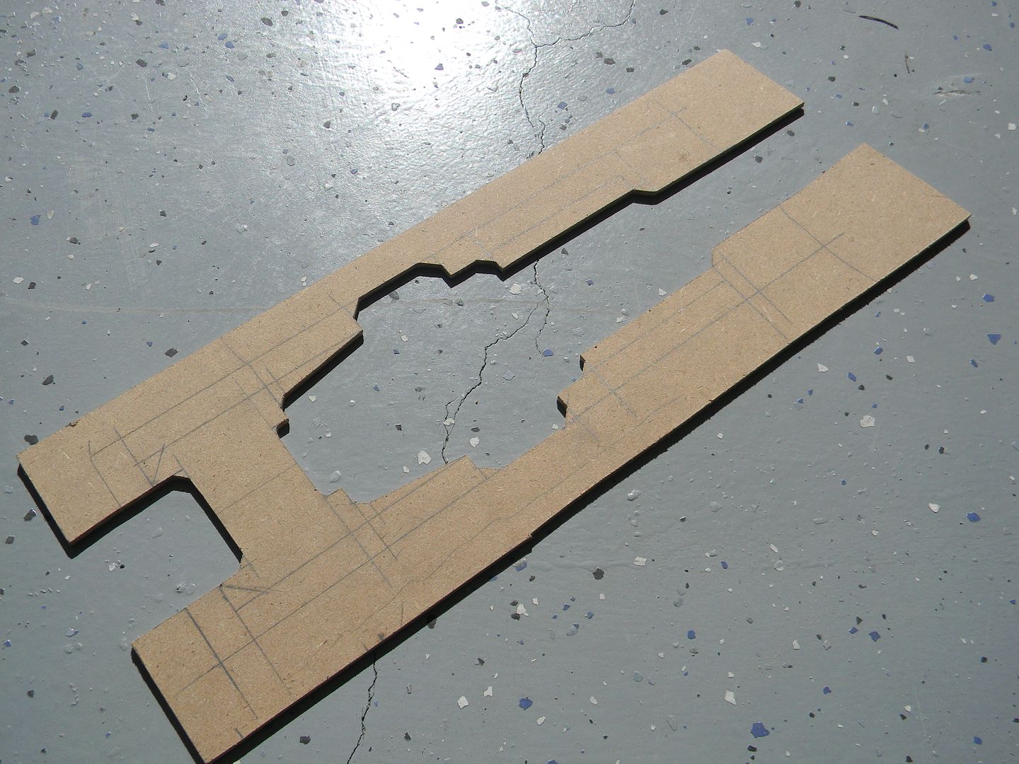
Then I cut out the bulk of the areas that need to be cut out, making it much easier to line up the scroll naw blade with the little detail areas.
The same was done for the "ears"
This is what I do when I don't want to wait for wood glue to try, I don't have any leftover clamps, or I don't want to babysit the part and wipe away the excess wood glue in the detail areas as it slowly seeps out. I use trusty old super glue, and spread it with a small piece of styrene to reduce high spots and make the glue go farther. (you'll eat up super glue like crazy using this method, but it is the strongest, fastest, and most consistent bond.) You have to do each side much like contact cement, then sand it down , and do a final glue. It will bond instantly, so made sure you have your stuff lined up perfectly.
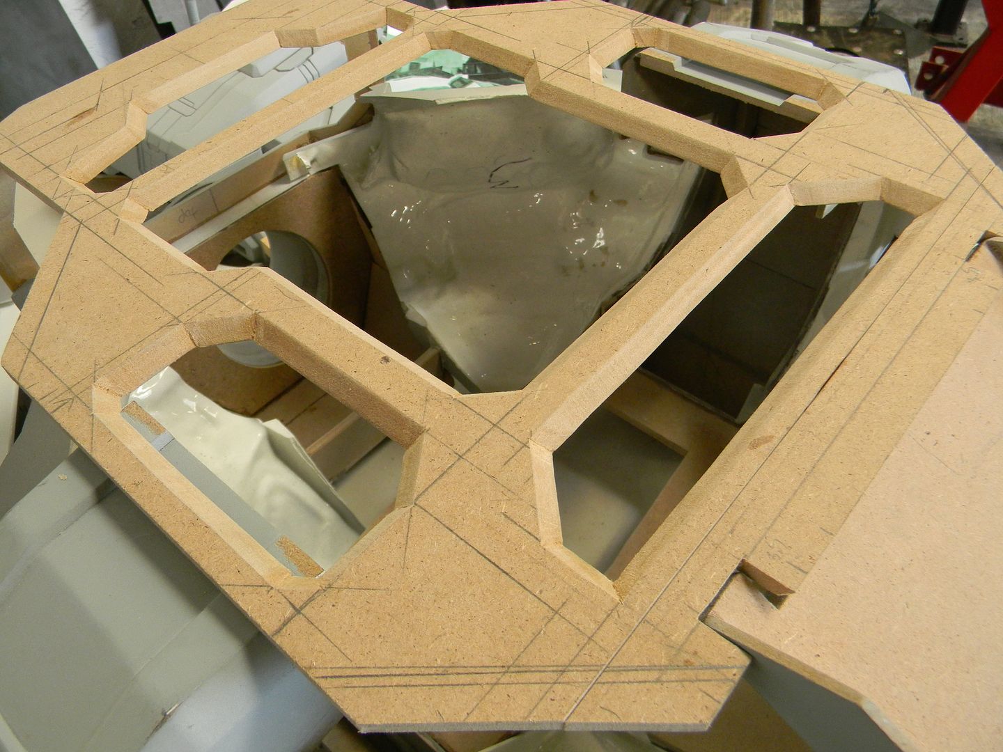
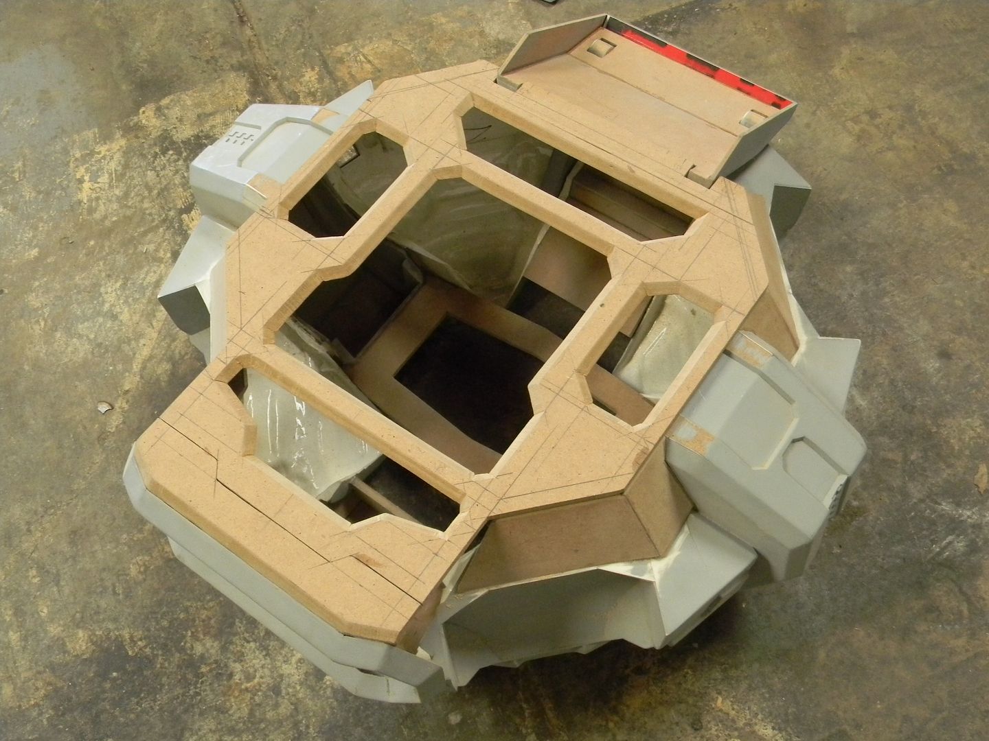
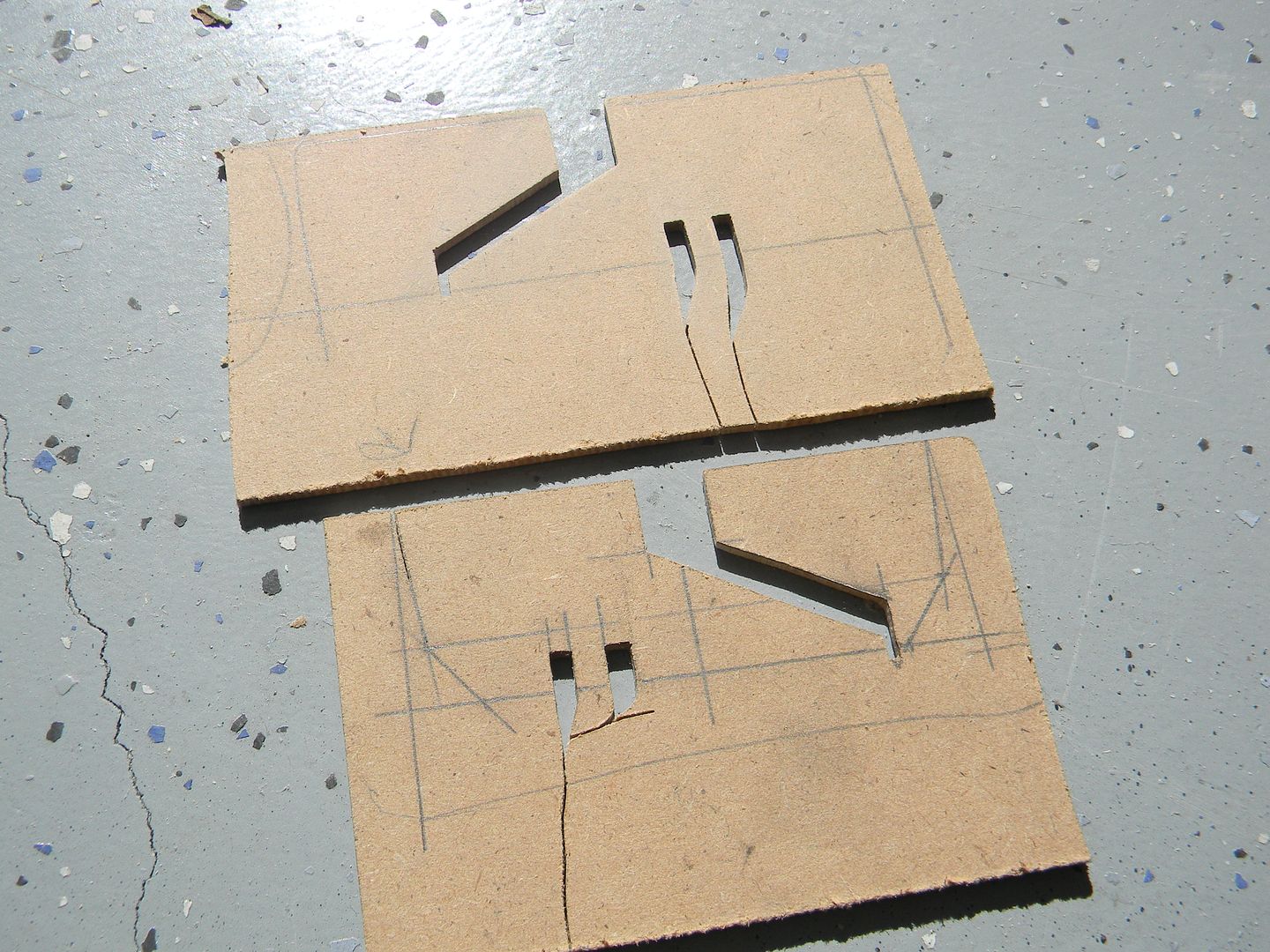
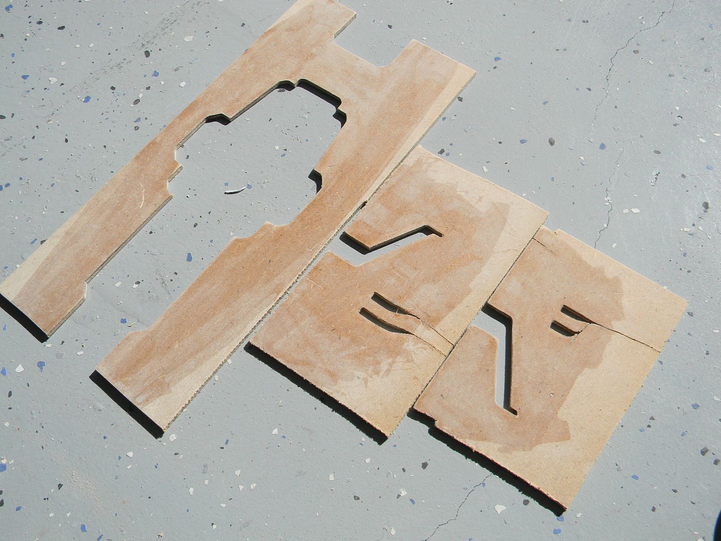
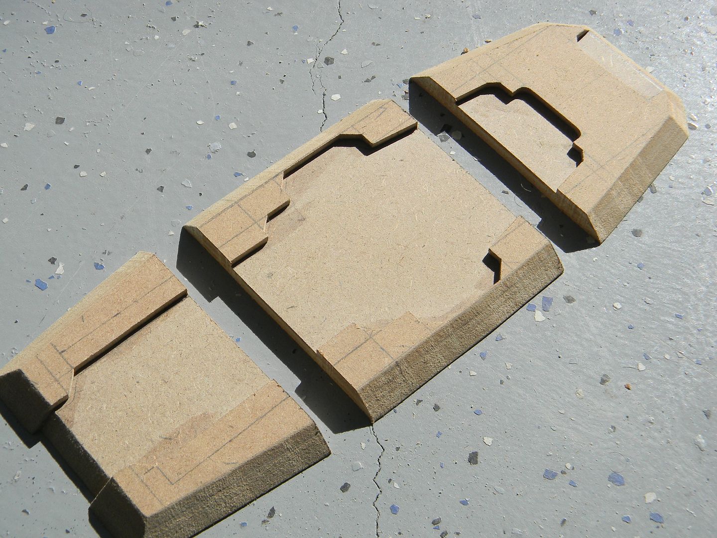
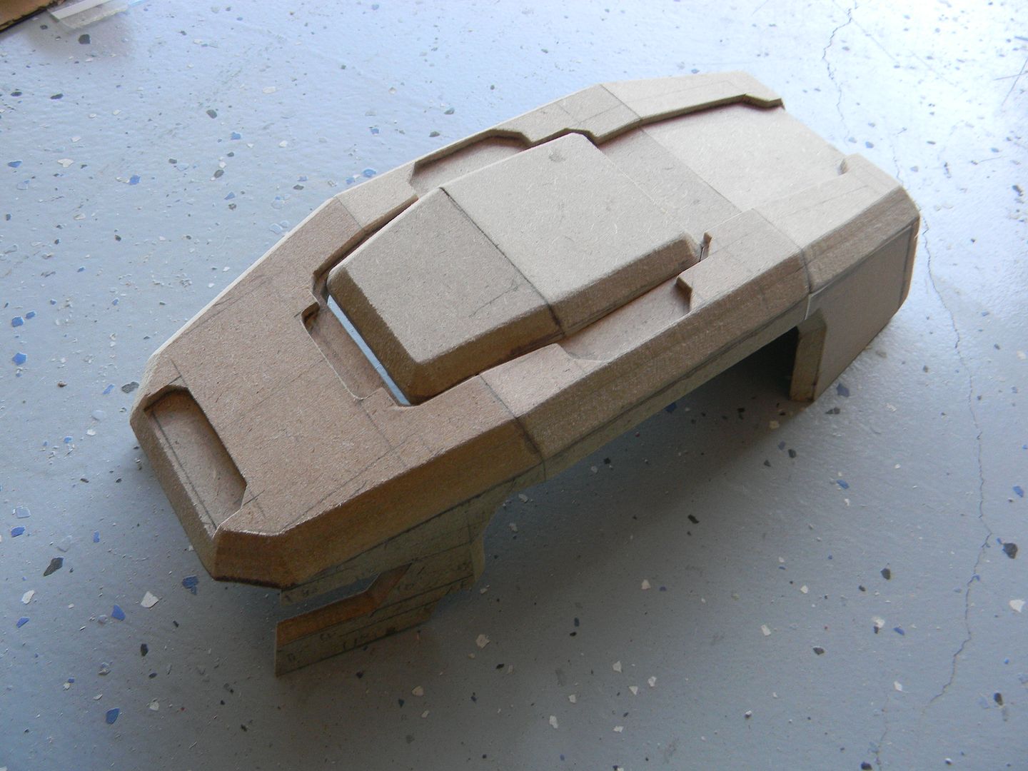
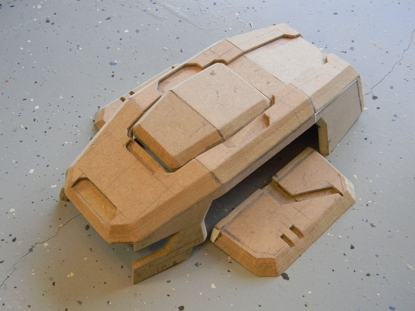
With the roof of the command module laminated, I can draft out the outline and cut the shape as one.
I had to cut the pretty looking roof into 3 sections, then taper the edges to make the bends in the roof.
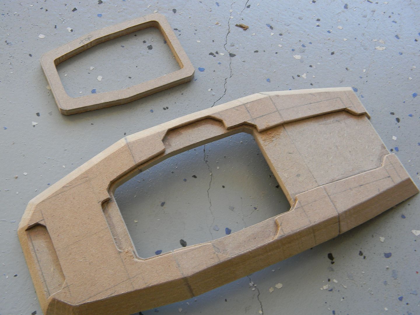
Plan stuff early! Here I need a hollow area in the roof to account for the top most panel, which doubles as the power switch. With the roof in sections, it was easy to cut out before assembly.
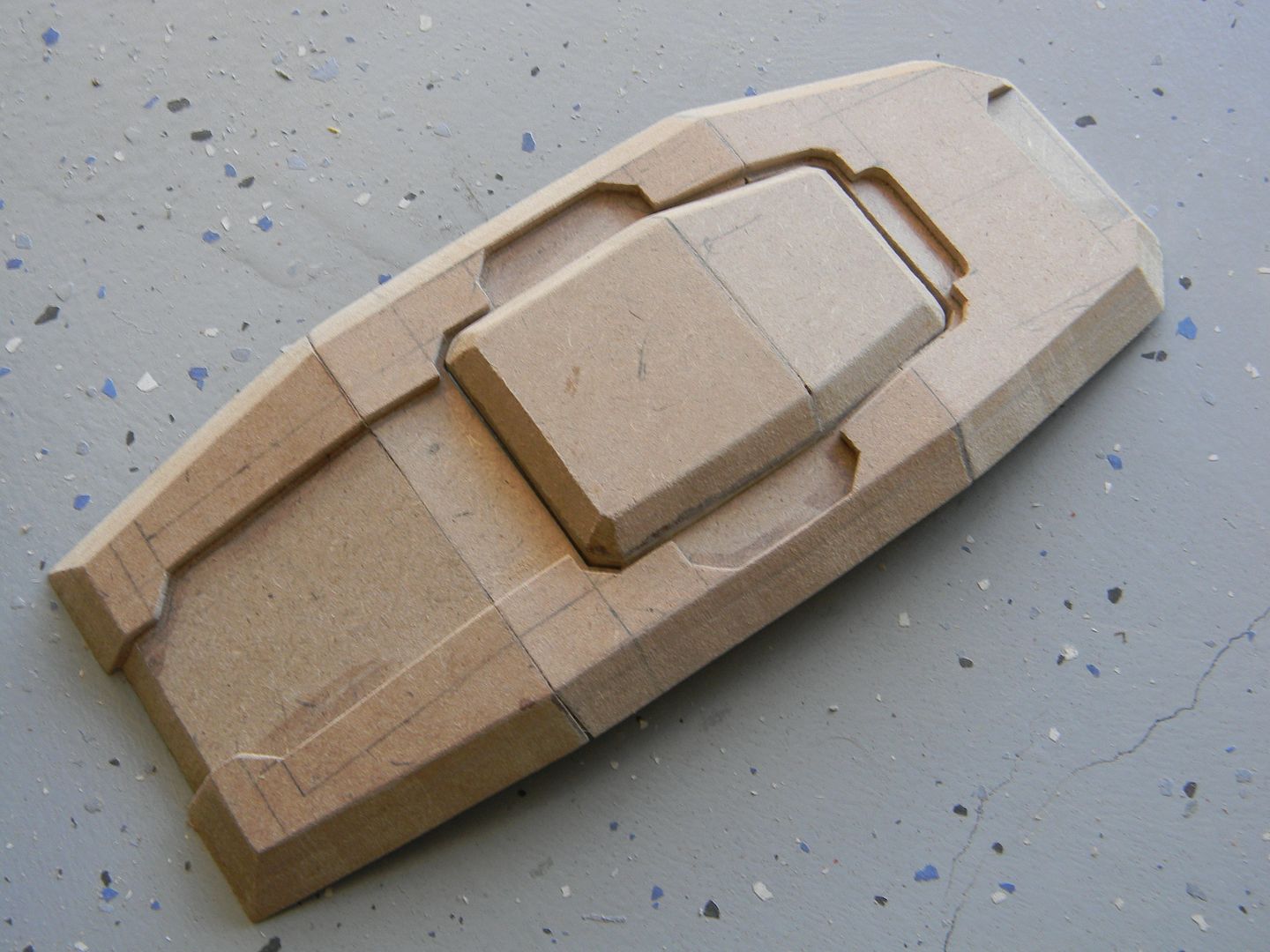
The button was made using the same principle as the roof.
Next was the sides. Here's an example of how I keep track of bevel angles when I need to make a mirrored, symmetrical version of a part. It is flipped over, traced onto the MDF, and the opposite side is cut.
Some progress on the ears.
If it doesn't look to pretty, don't get discouraged. You'd be surprised at how nice this stuff cleans up.
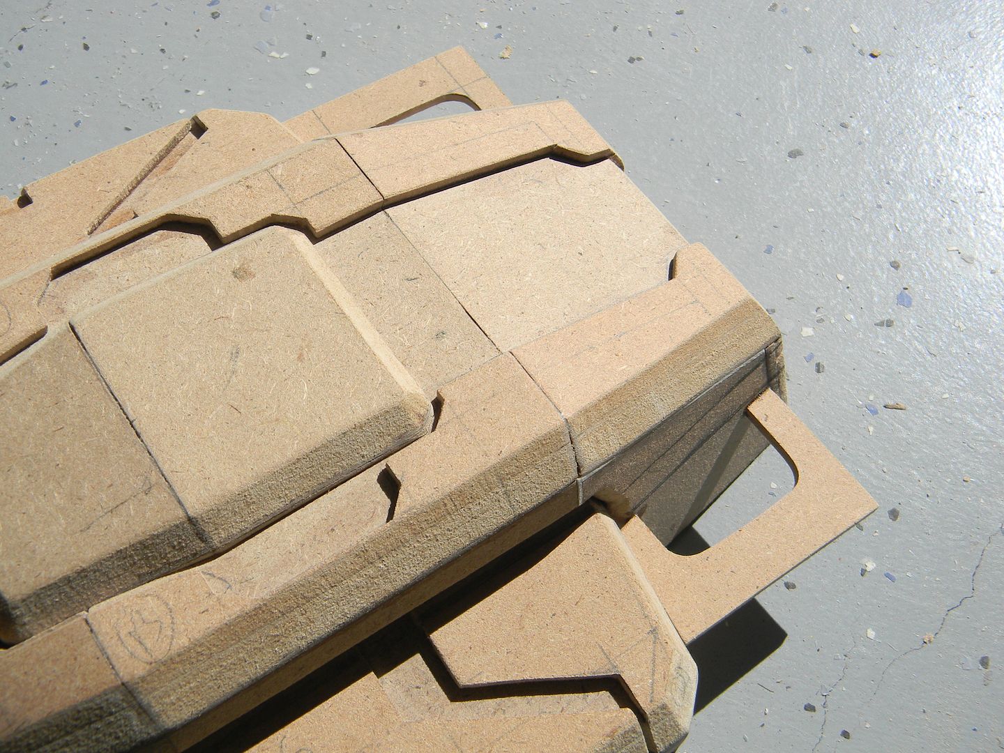
Jumping around a bit, I decided to do some paneling above the front door while the method used for the roof was fresh.
Starting to see a pattern here?
Took a little progress shot here to motivate myself. This is after tediously sculpting the front face of the command module using styrene, a nice pair of ergonomic fiskars, and an exacto blade + metal ruler for scoring the styrene.
Behind the "ears" there is another set of.... ears! they also have a fair amount of detail. Nearly cut my finer off doing these on the saw.
This is the basis for the lower half of the front paneling. It was also cut into sections, laminated, and glued at angles.
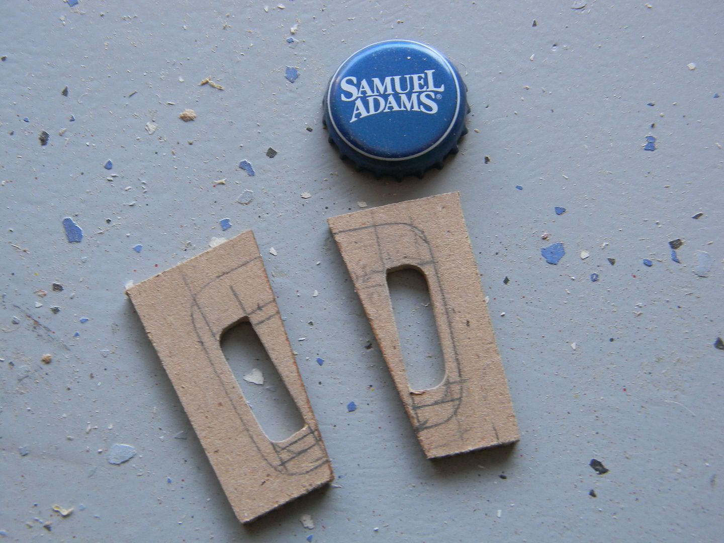
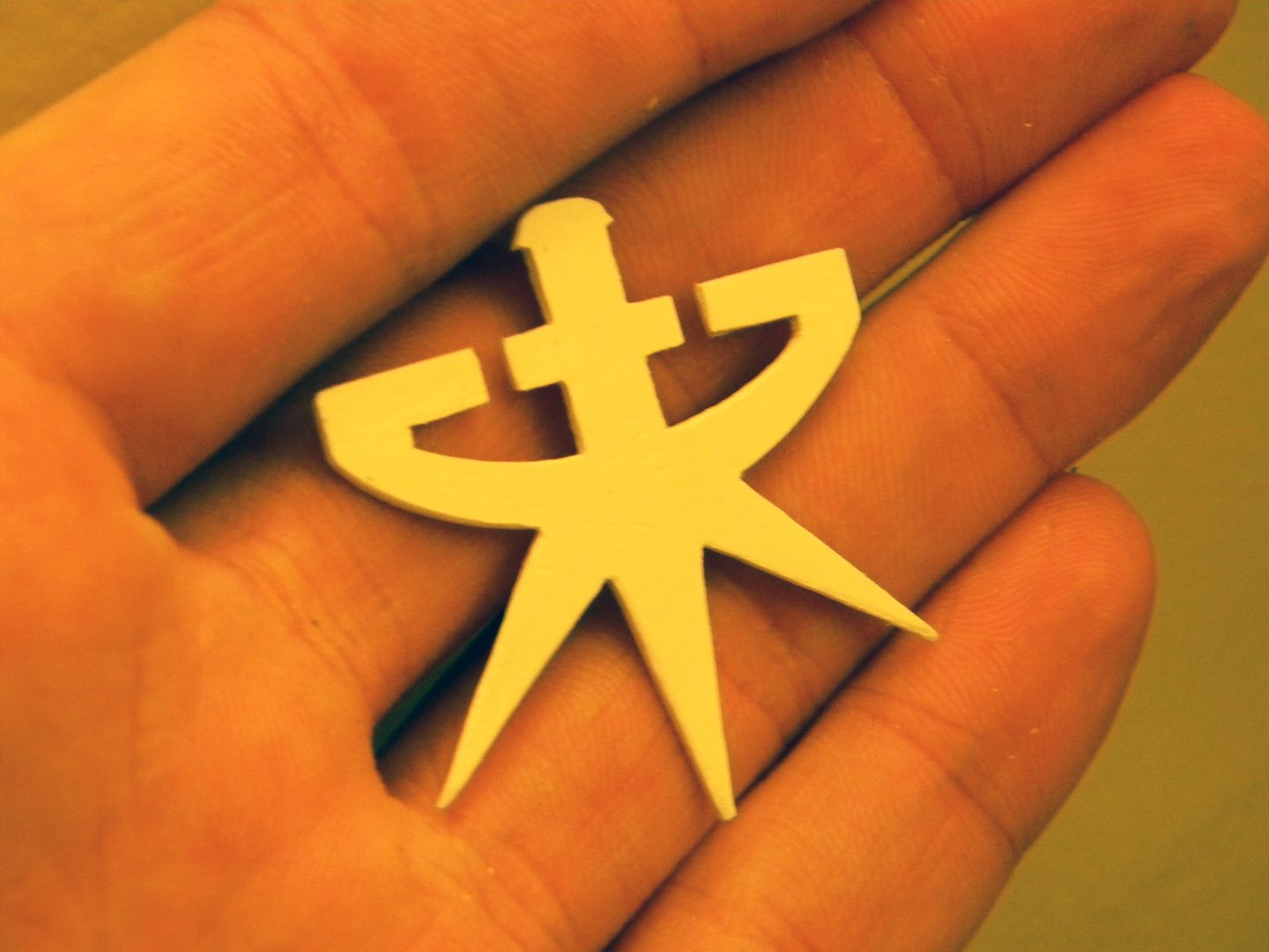
this was the first logo I cut out. (By hand, just good ol' scissors and an exacto for clean up.)
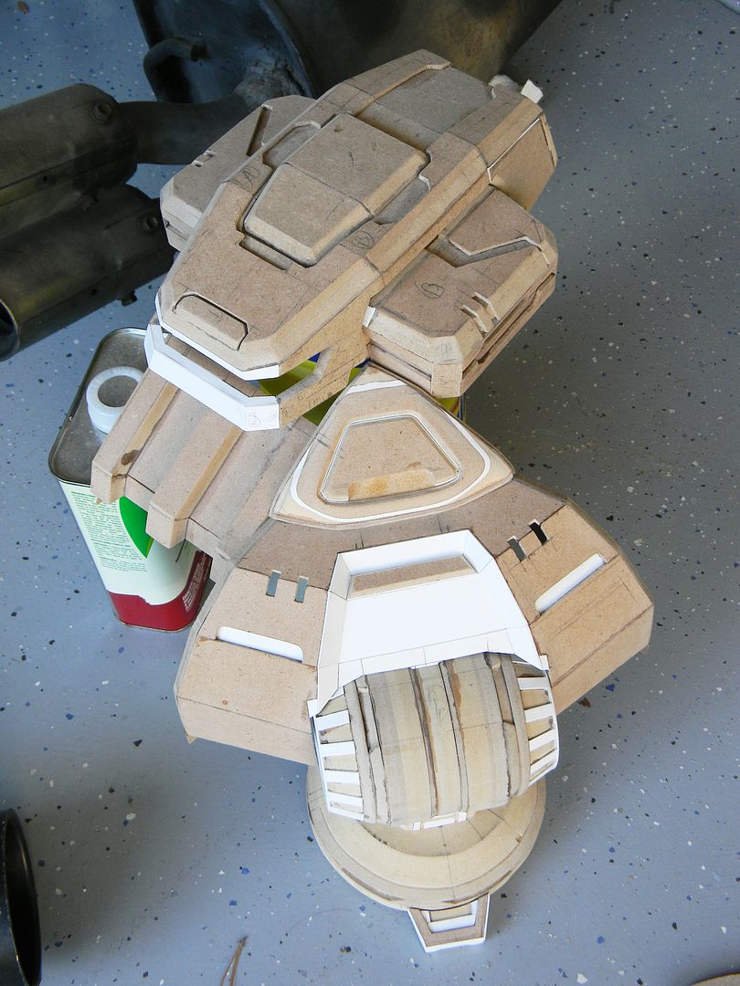
More styrene details, and current progress of the front:
"
What is this? A center for ants? How can we be expected to teach children to learn how to read... if they can't even fit inside the building?" - Derek Zoolander