Where were we....
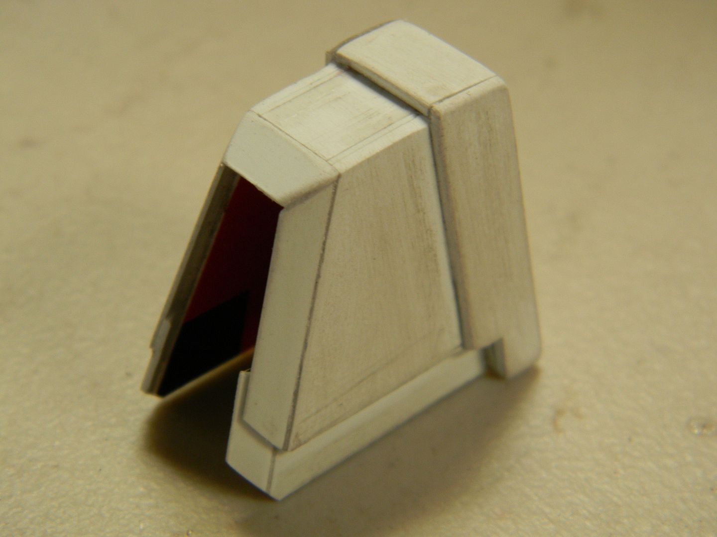
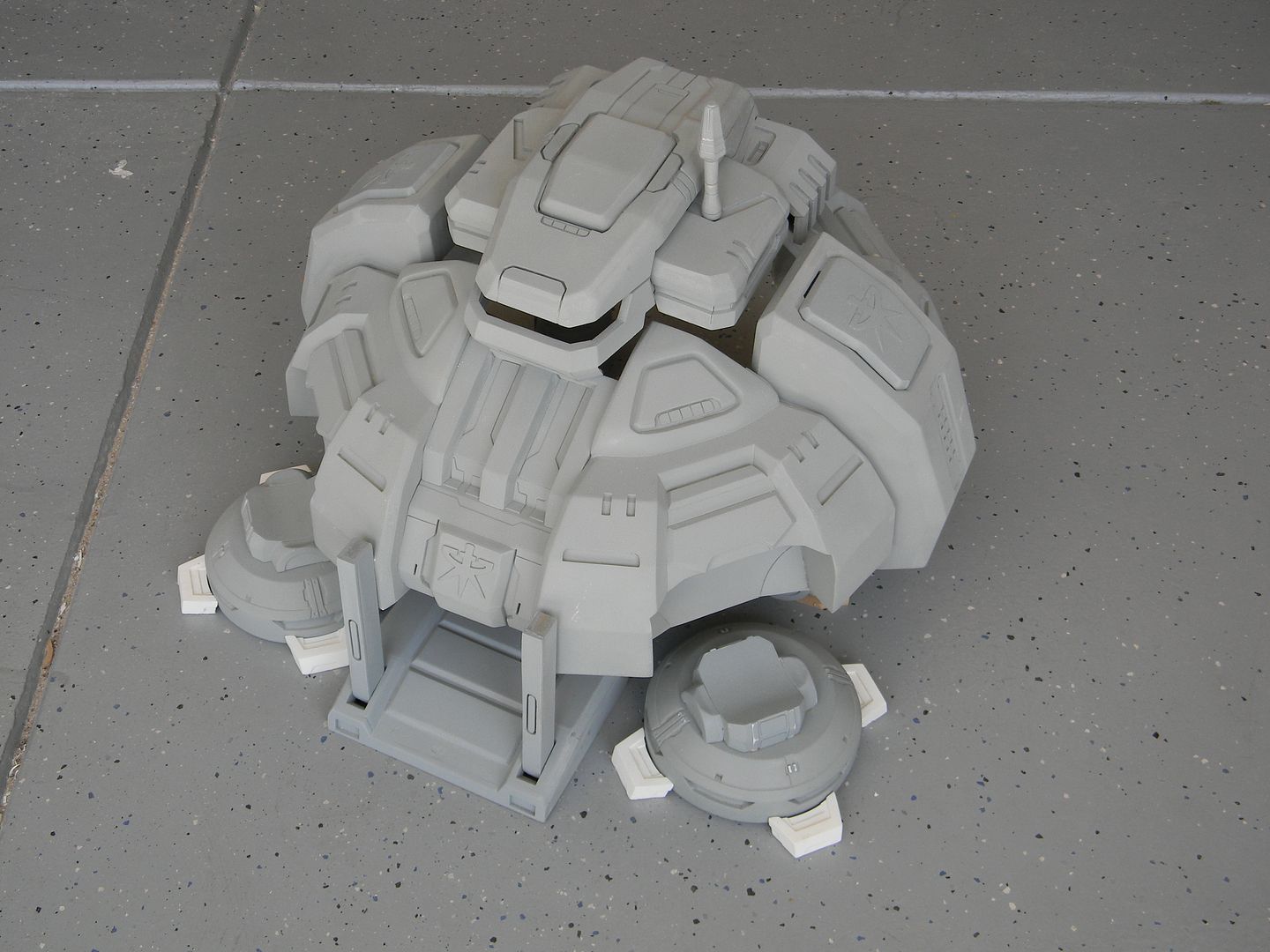
The front door of the command center is the only part of the command center that actually "works" when it lifts off. By that I mean it is the only part that doesn't "clip" into the body or disappear/appear from nowhere. Originally, I wanted the option to go back and add a "partsforming" function to the command center by swapping the straight leg assemblies with an extra set of ones that are curved in for lift off. A functioning ramp was really all that survived of the liftoff idea, as the legs simply "clipped" into the body too far.
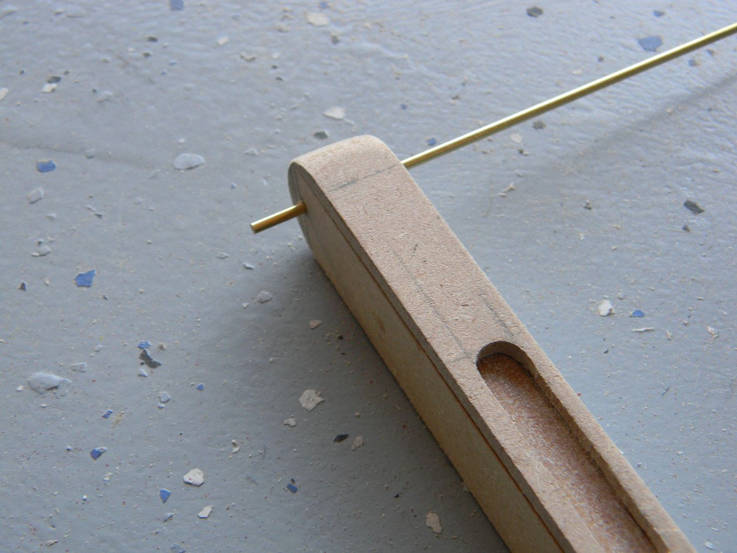
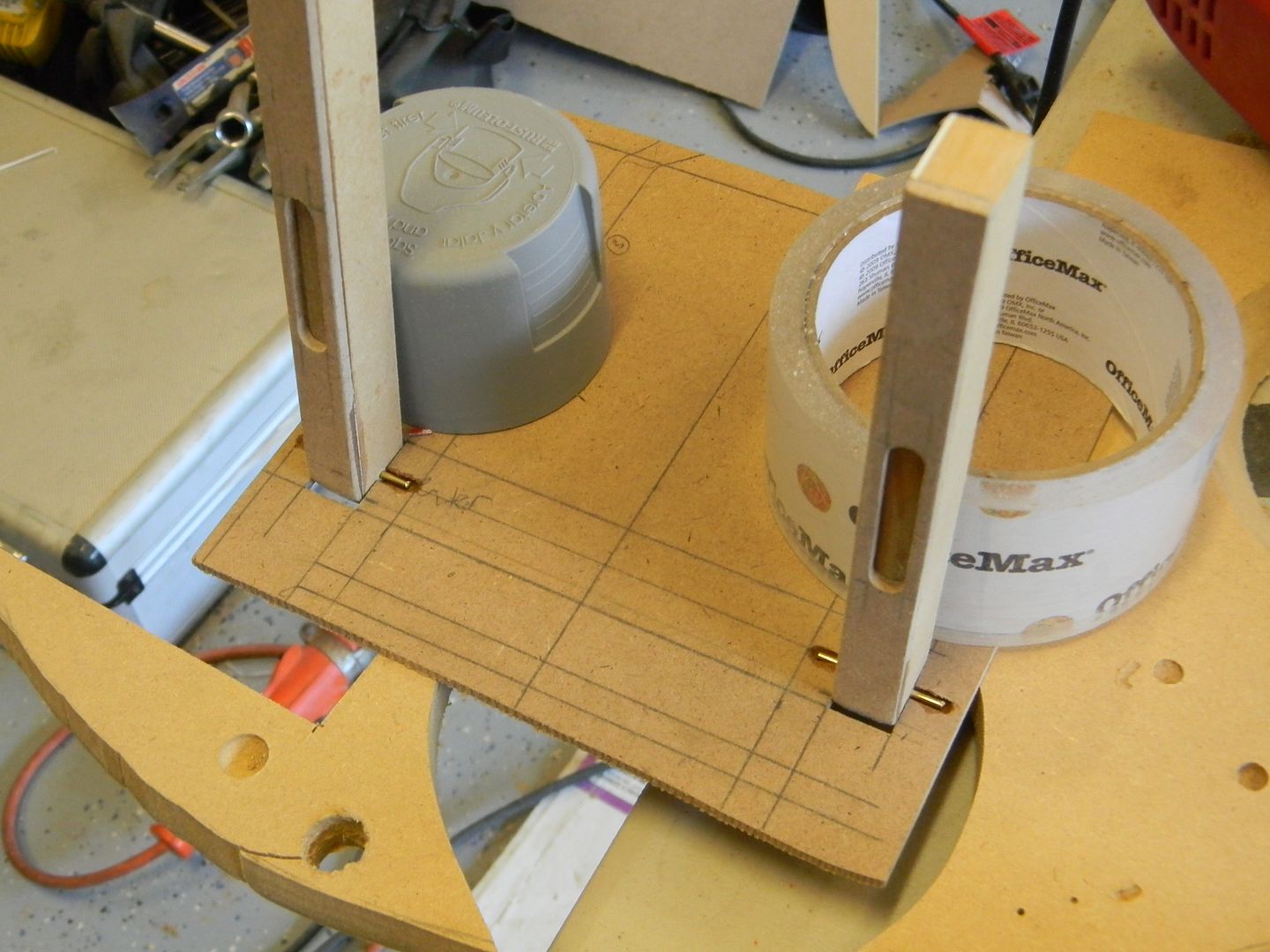
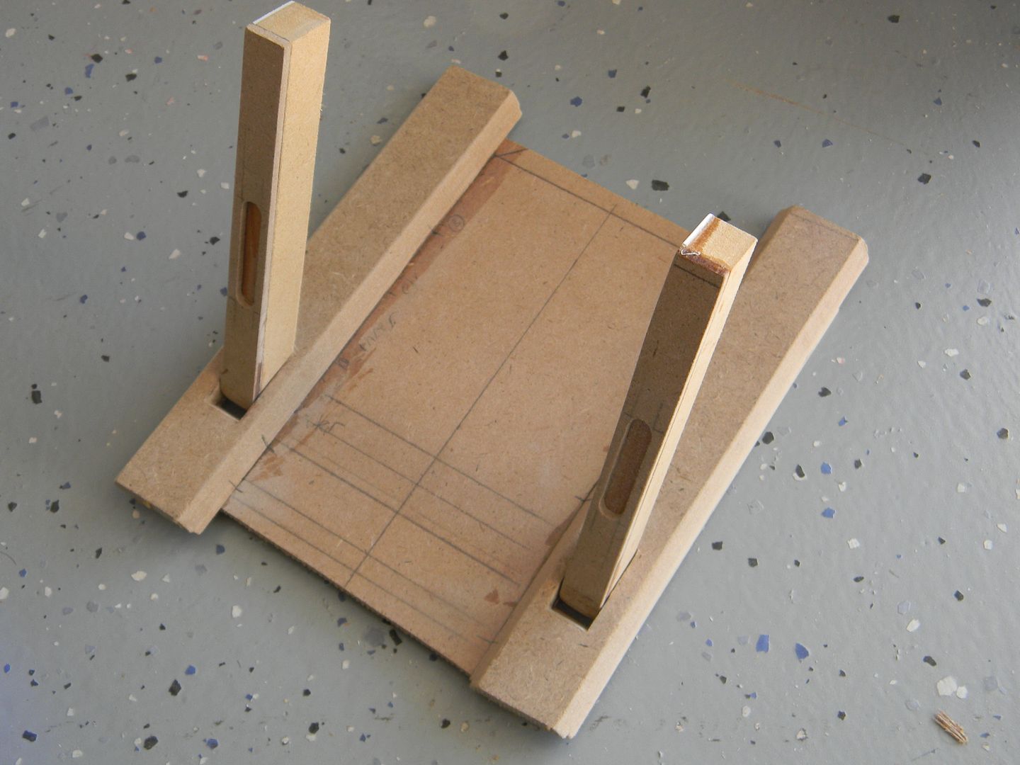
Instead of a conventional hinge, I decided to use a small brass rod that went through the door posts to allow them to swivel.
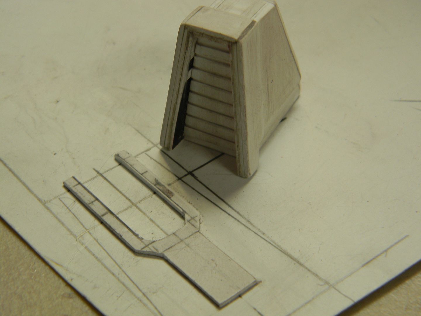
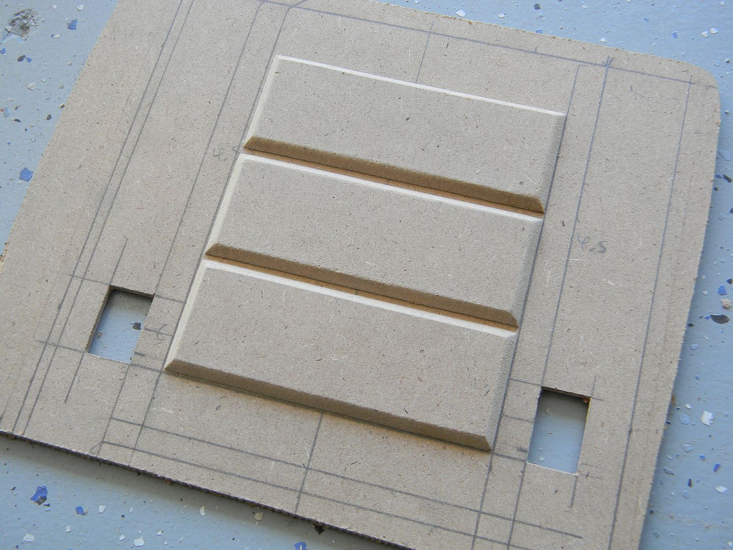
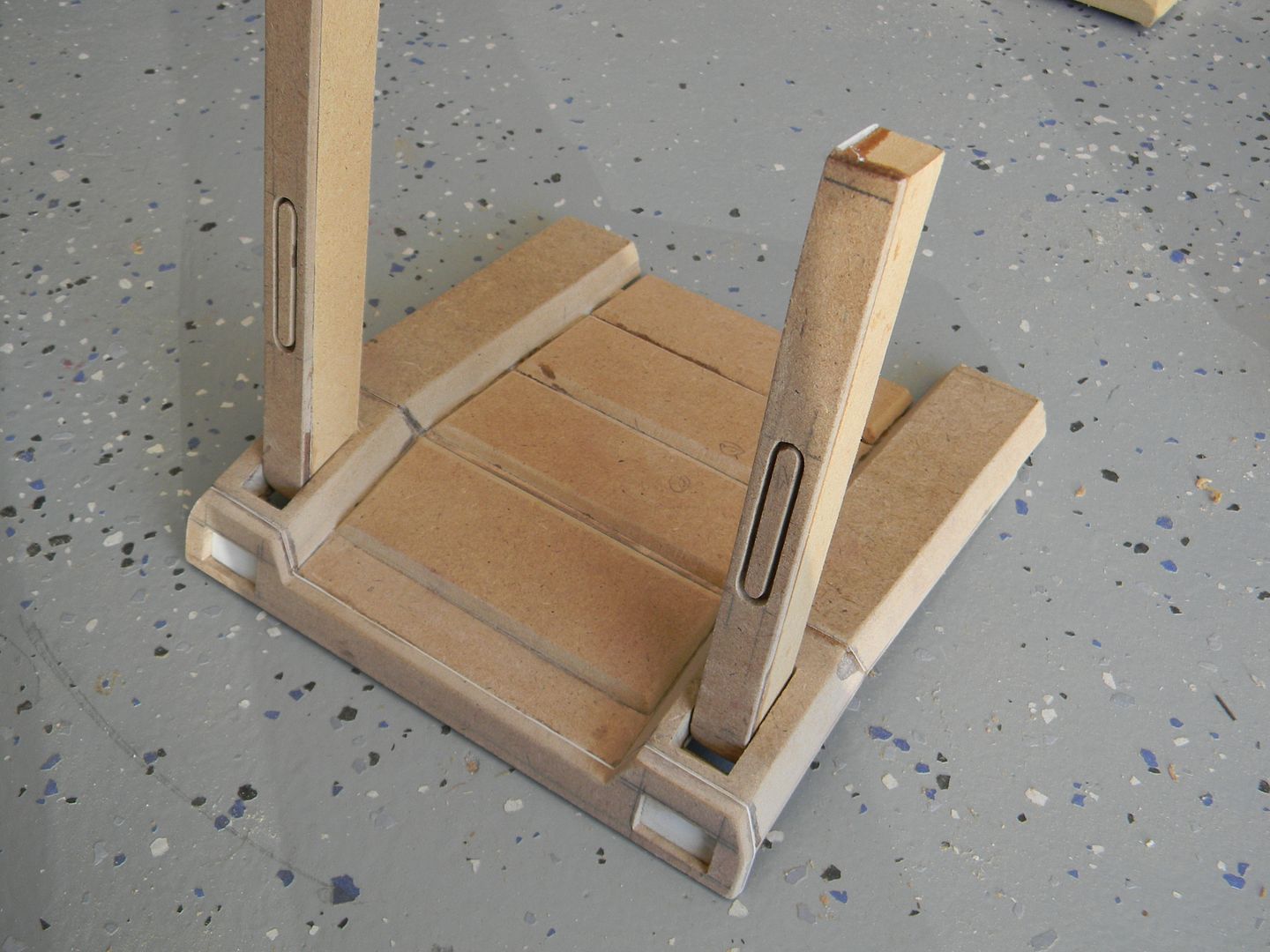
I then went about making the ramp itself, dry fitting some paneling to test the general size/spacing.
With the pattern decided upon, I dremeled tiny notches for the brass rods and glued them in. Afterwards, these rods would be sandwiched with more MDF to be very sturdy.
At this point, there was no going back as far as the hinge assembly goes.
The rest was just refining the ramp. There is a slight kink in the design, which is why I decided against laminating a munch of flat sheets. Also, with a hollow, lighter weight it will stay closed much easier.
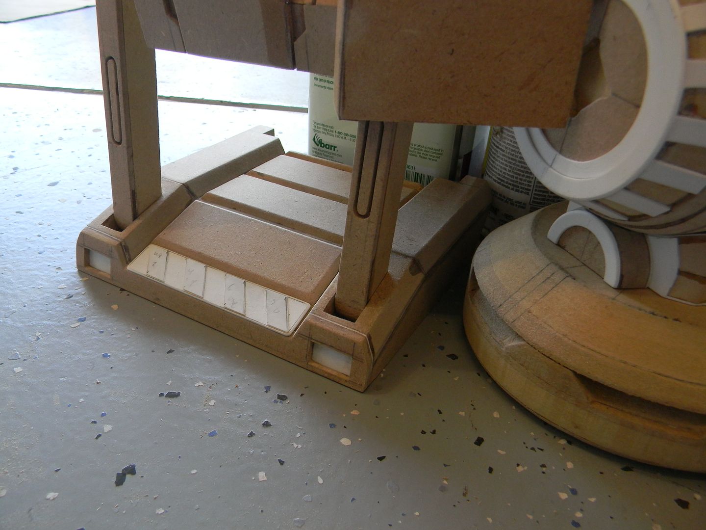
I had to be sure the ramp wasn't too wide, to deep, etc. or it would interfere with other parts and have to be trimmed, or more importantly, wouldn't be able to close. Luckily, it all worked out perfectly in the end.
Until I had the bottom of this thing done, I couldn't go much further and started the next assembly.
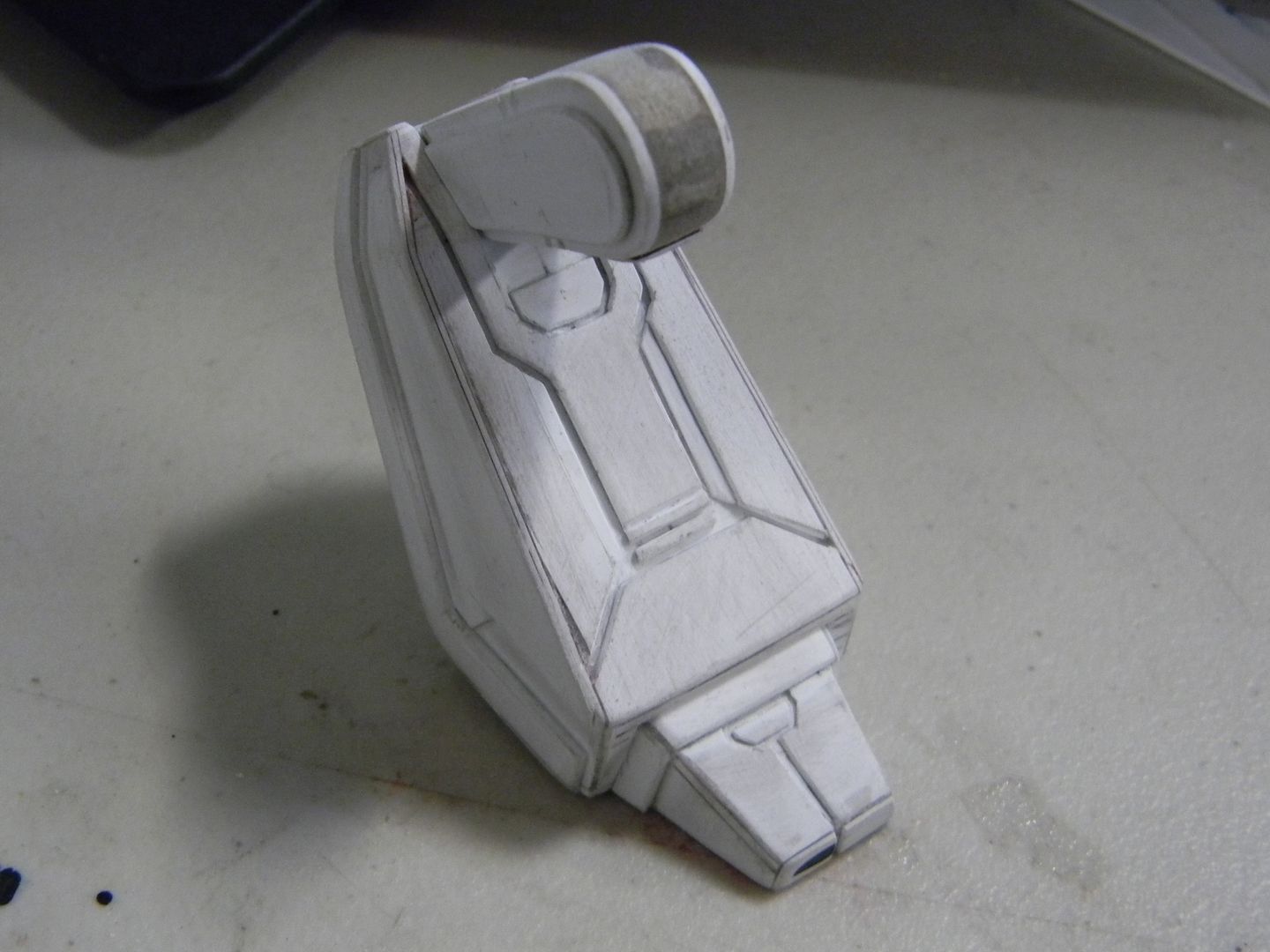
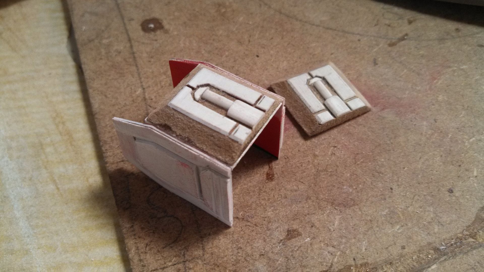
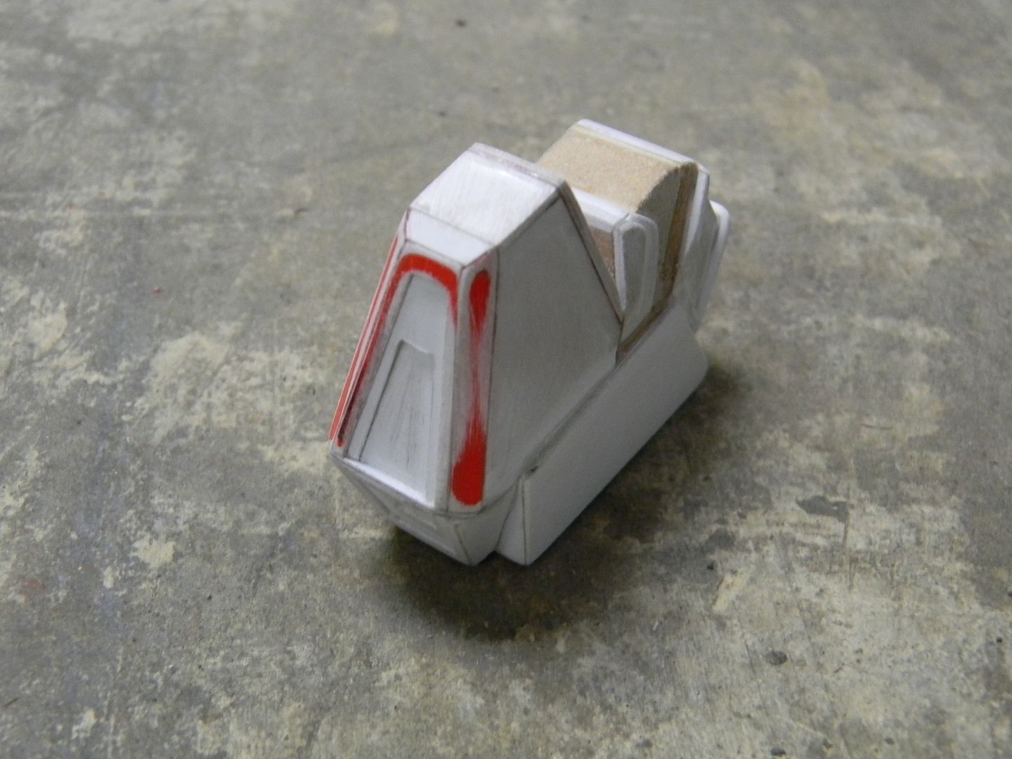
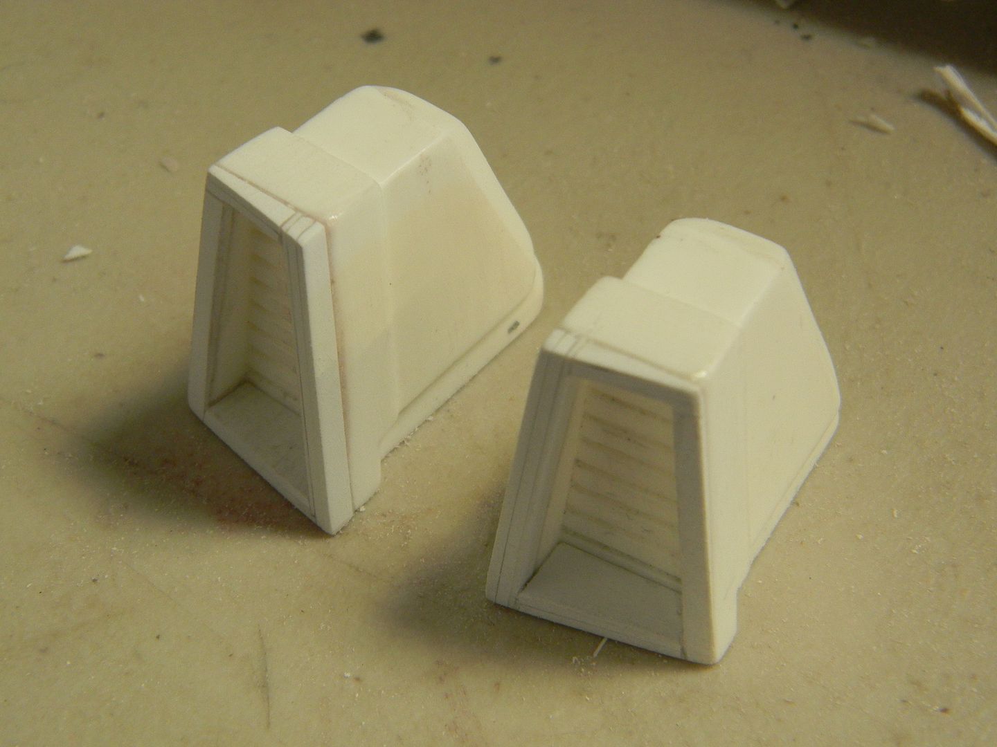
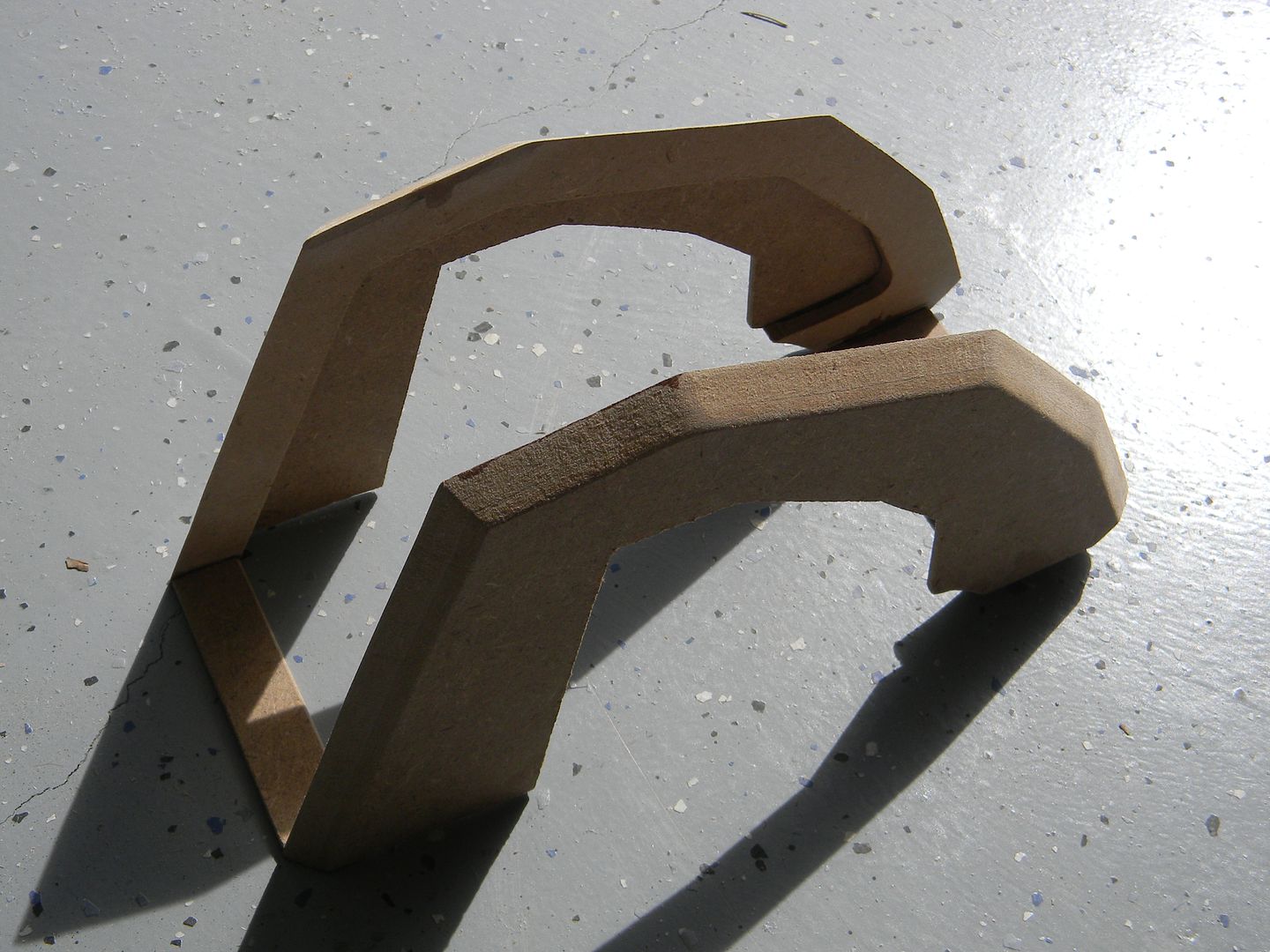
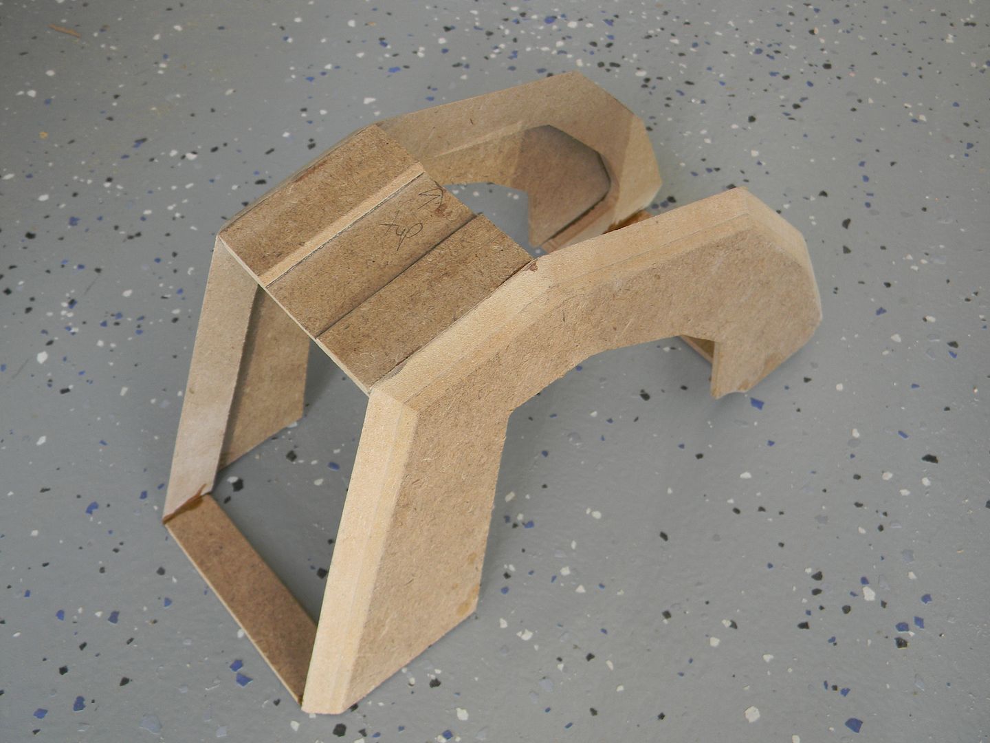
I decided to start on what I ended up calling the "side modules". they protrude on each side of the command center and while having complex bevels and subtle tapering, don't really have as much detail as the rest of the command center until you get into the little channels on them. They are exactly the same on each side, and typically I would mold them so I didn't have to do it twice. However, I decided just to tough it out and make the two from scratch and save myself some silicone.
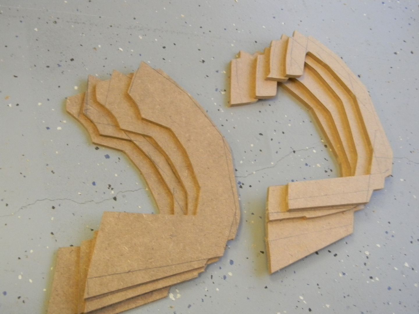
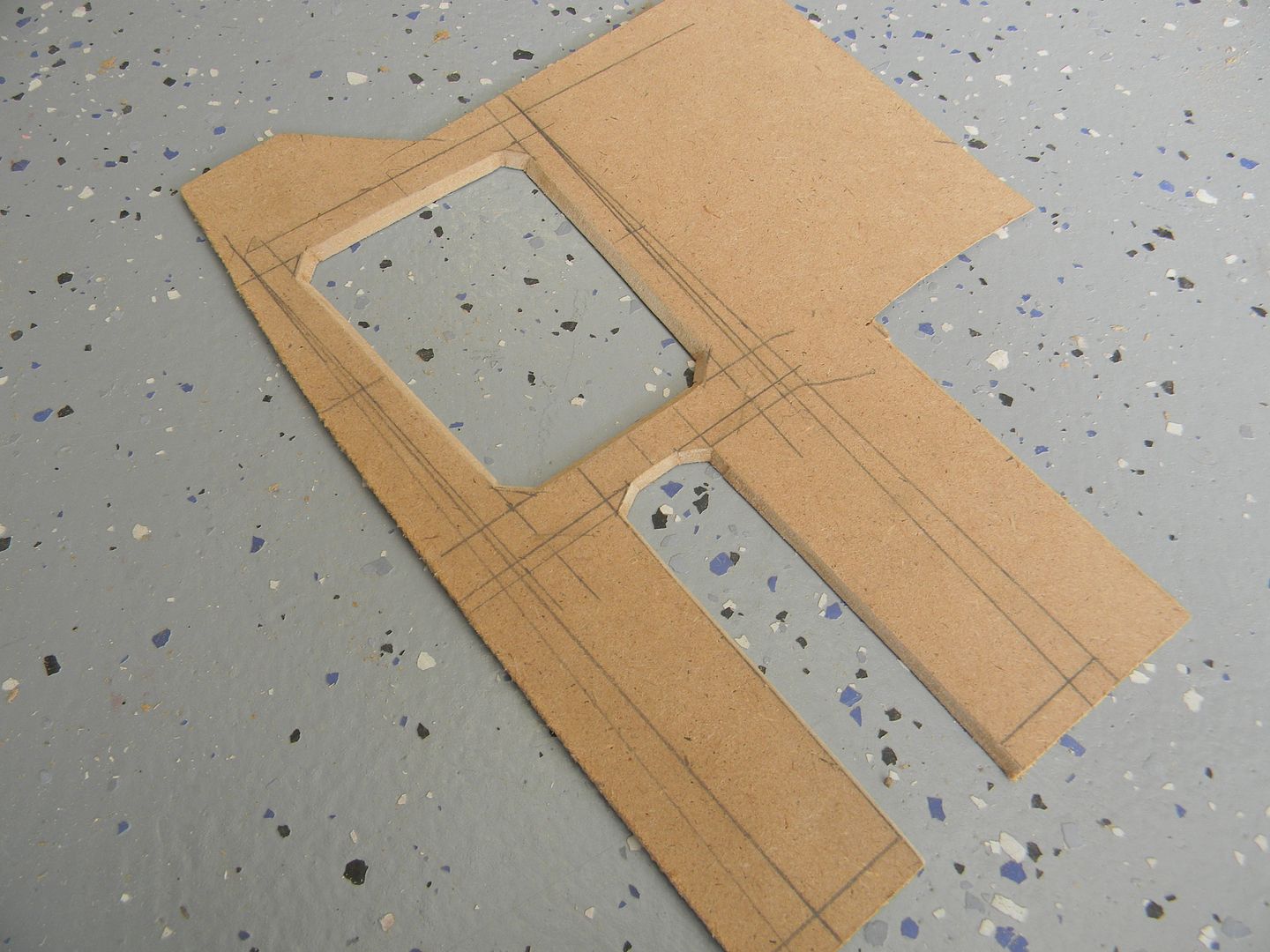
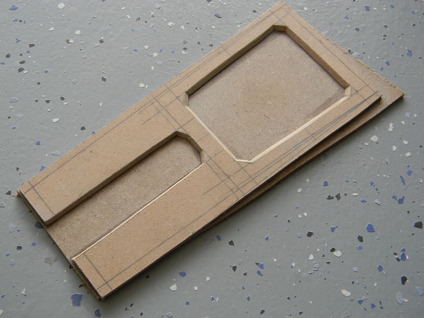
I made a template, and traced out the sets for both sides. These would get laminated together, and then cut since they had a pretty specific thickness.
You can see here how the outside layers are the larger, thinner layers while the inside layers are thicker but more minimal. I made considerations like this with anything I could that was MDF and wasn't going to end up being replaced with a plastic cast.
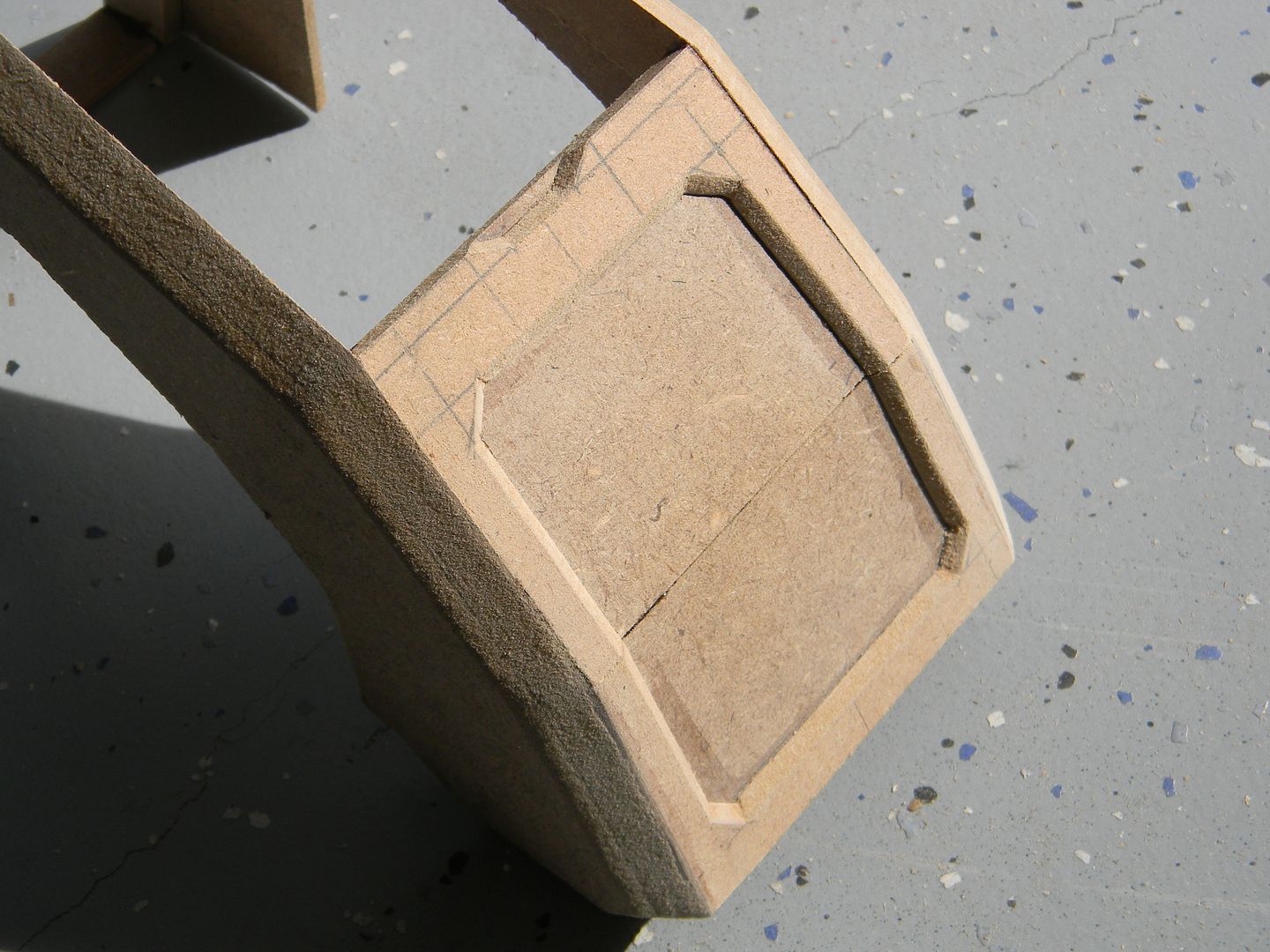
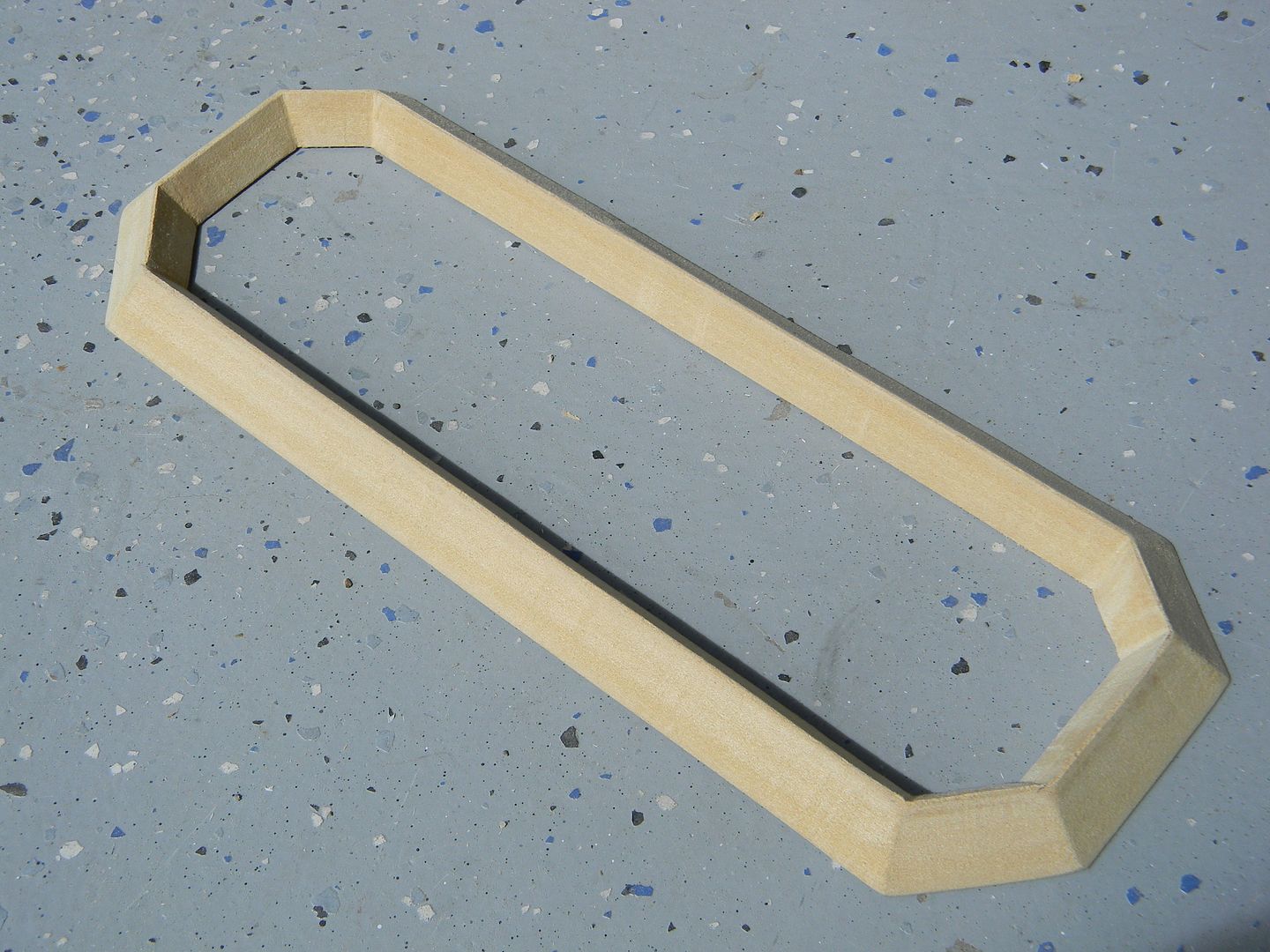
I started making the skin around the modules, with the "channel" already cut out. The module tapers in ever so slightly so I installed the spacers in the important areas first to gauge the size and angle of the taper.
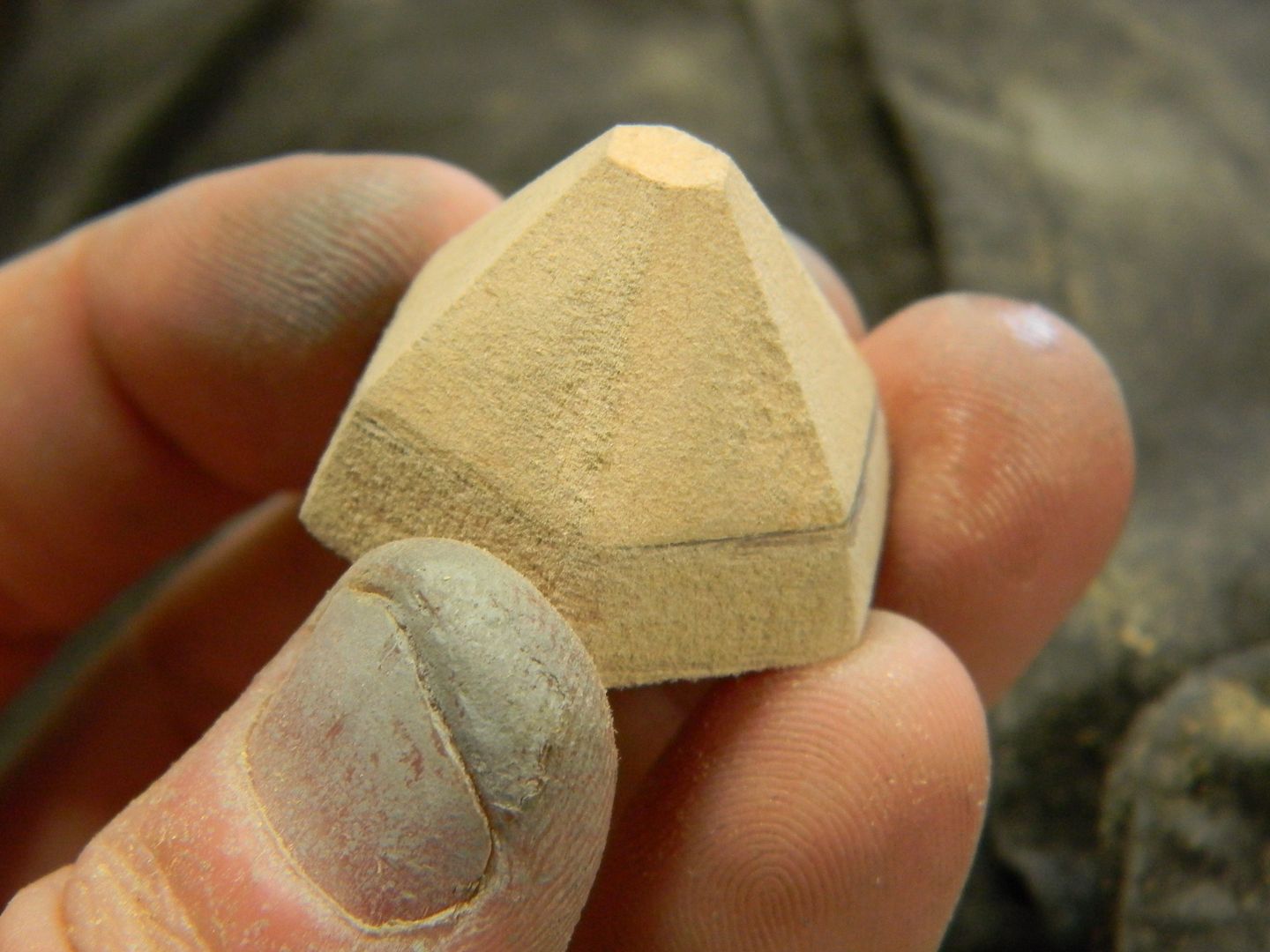
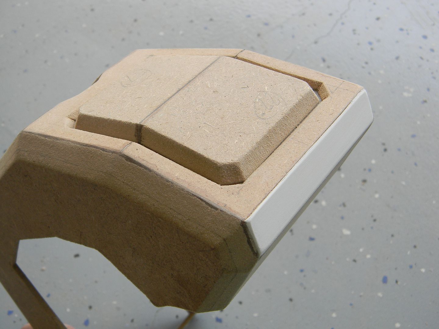
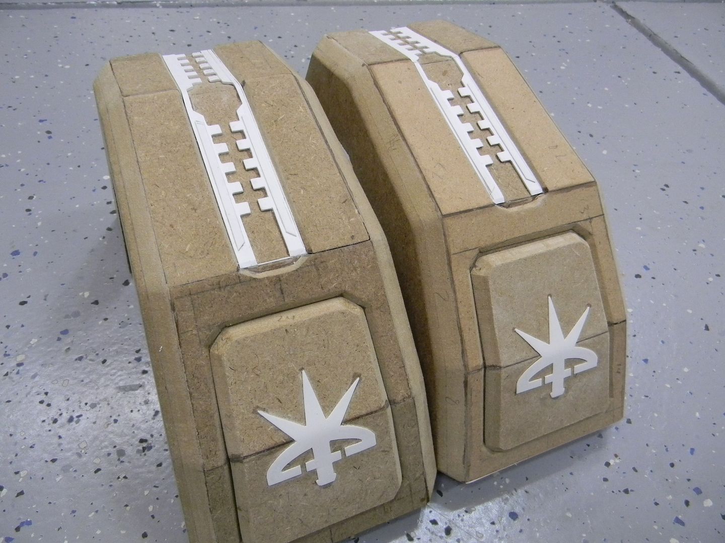
The skins have recessed areas for the channel, but also two panels that have the Raynor logo on them and draw a lot of attention. therefore, I needed the beveling of said areas to be as clean as possible. I spent a lot of time drafting these out and calculating the taper as it wrapped around the module.
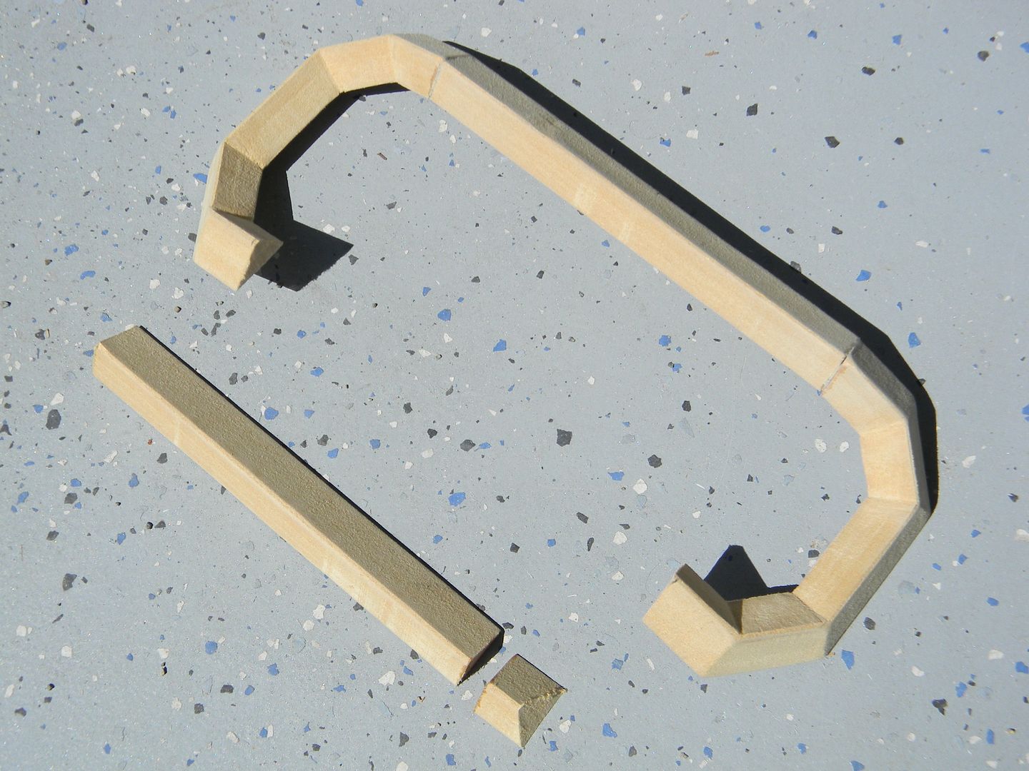
The skins were cut, re-glued, and beveled to match the frame.
Some times I use styrene for small bevels. The paneling was made to match, and comes off easily for painting and will also serve as an access panel later on.
I cut the logos out using the same method as before.
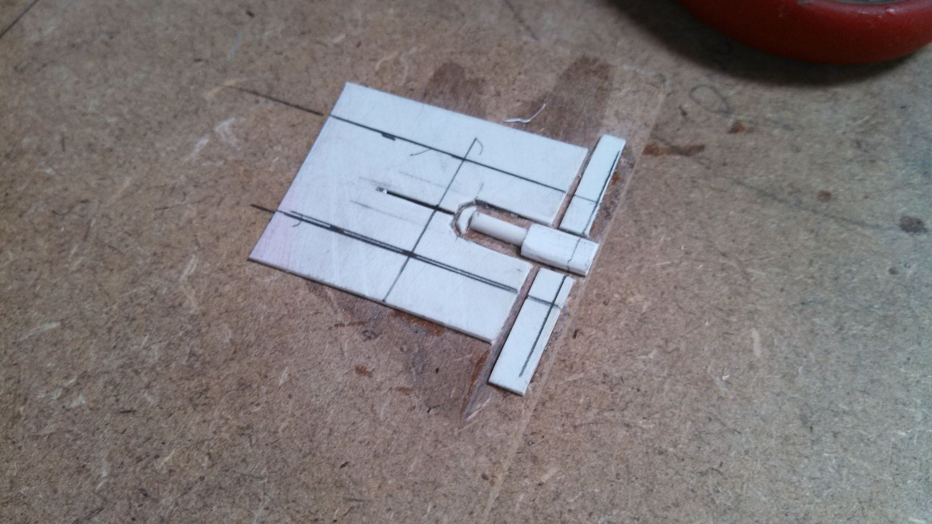
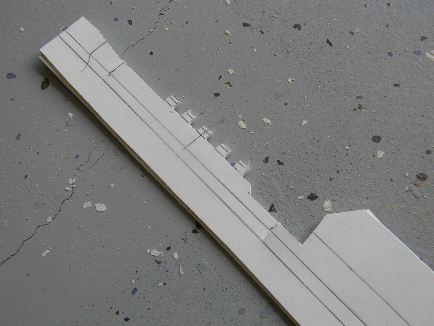
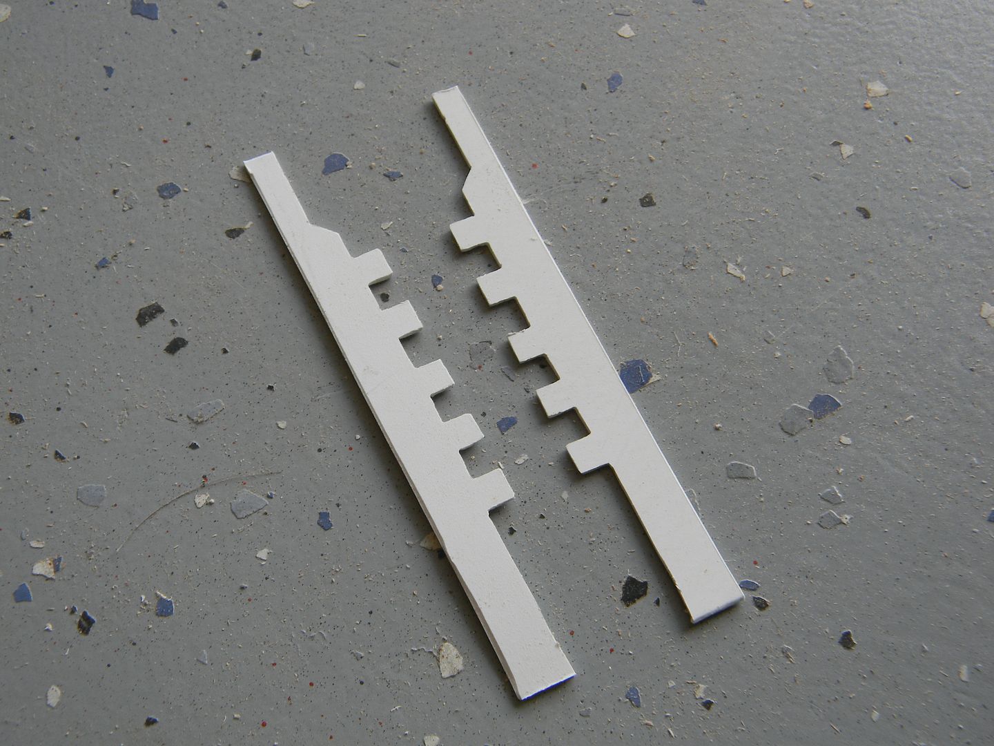
The details in the channel were drafted out on a piece of styrene, then it was lightly glued to another piece, then cut at the same time on a scroll saw.
The result is two perfectly symmetrical parts.
I decided to do the first pass of primer and a light sand before installing the modules.
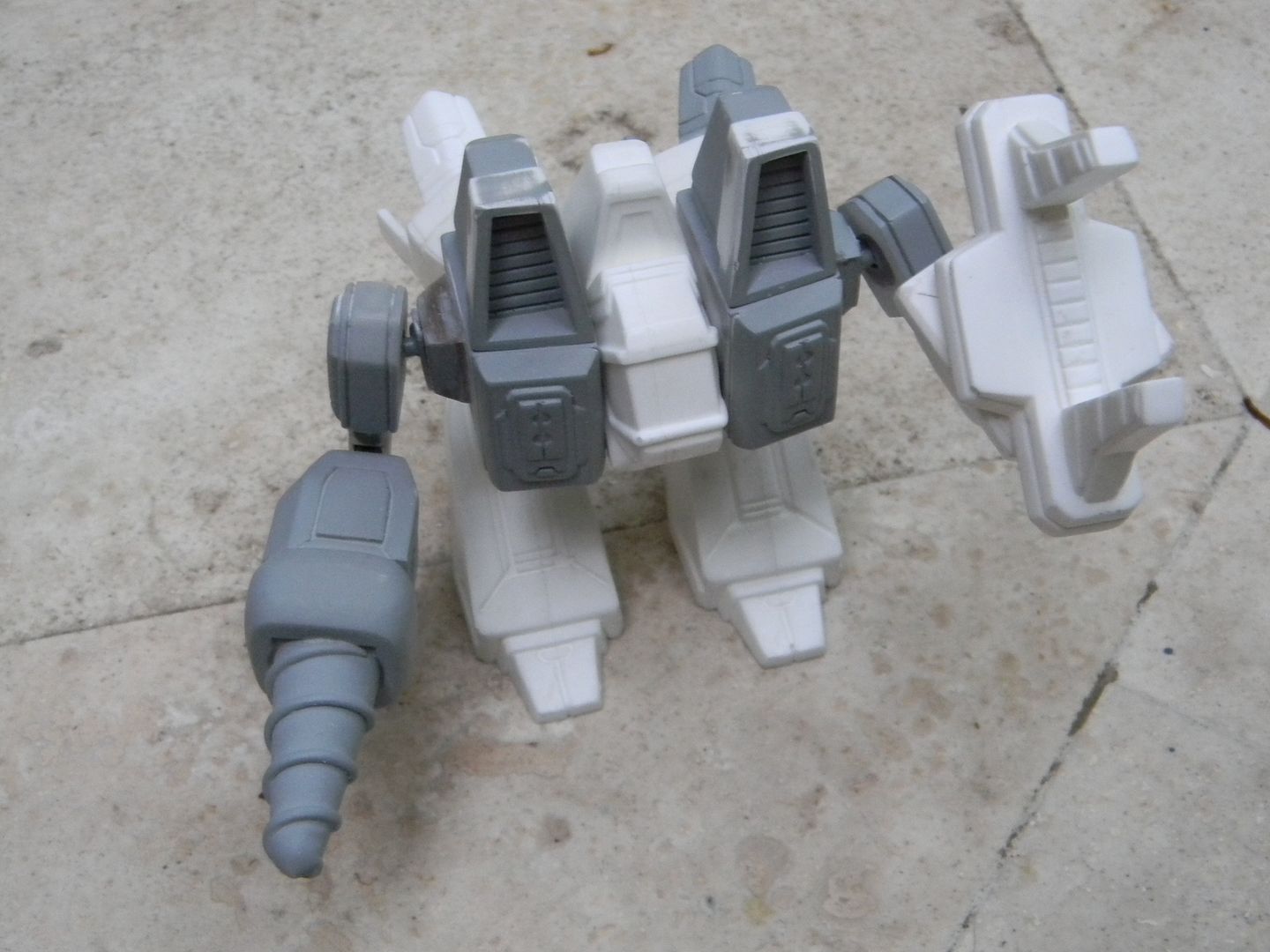
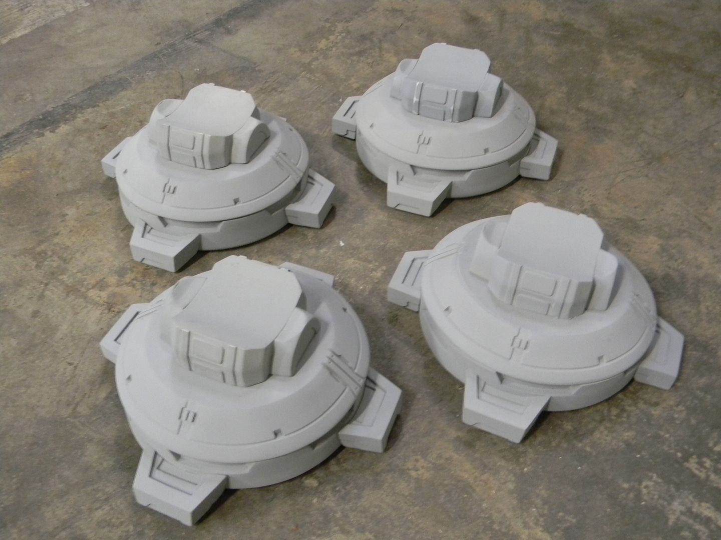
The corners and feet needed to be completed before the thruster housings and underside paneling could be started. Reason being that I didn't expect perfect symmetry down to the hundredth of an inch when all of the cast parts came together! Im ambitious but lining all of these guys up one after another in XYZ space was nearly impossible to get perfect.
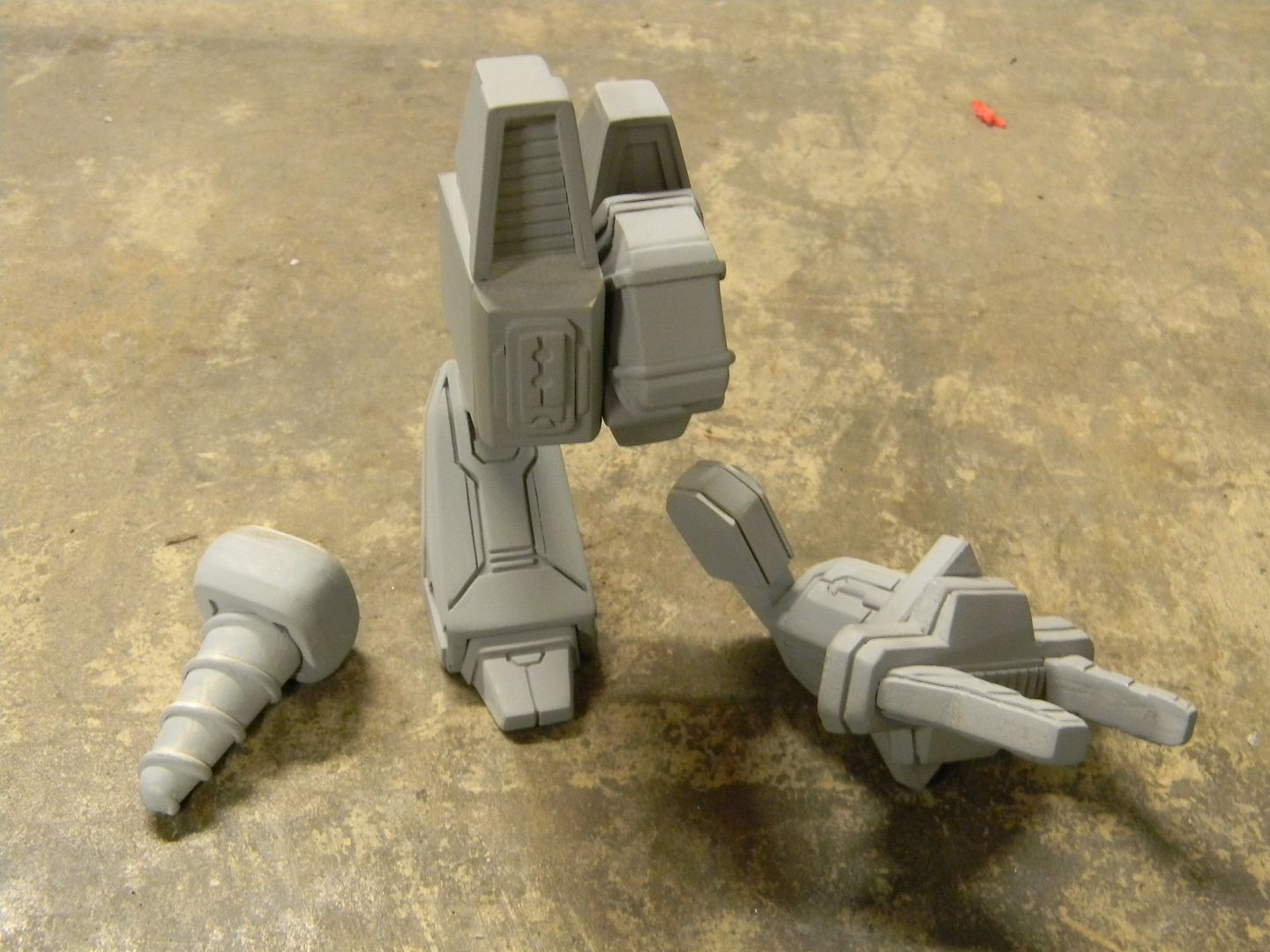
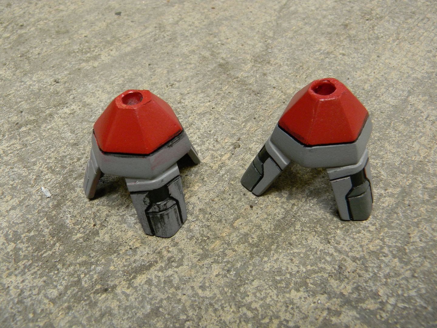
the knee was a pretty standard two part mold, utilizing and MDF jig method I've been tuning since early last year.
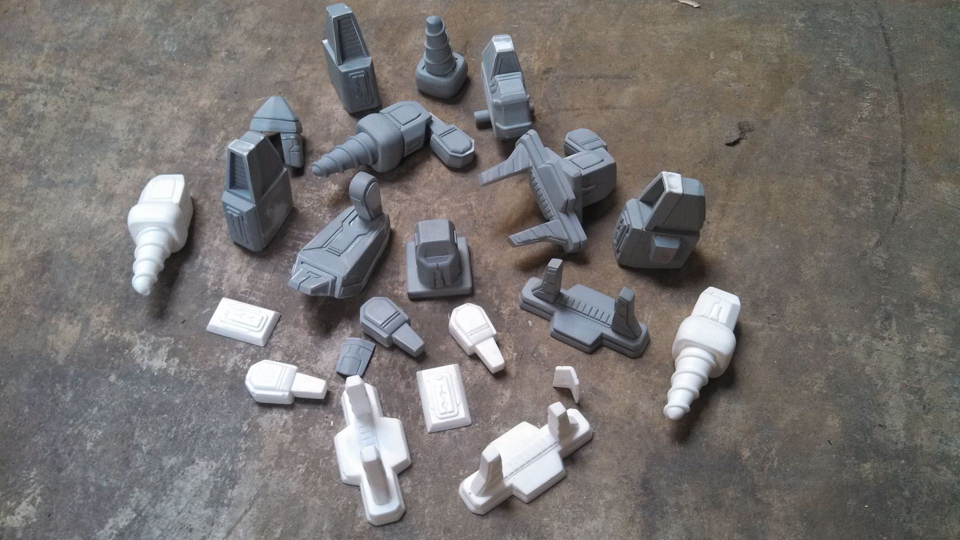
I throw in pieces from old/failed molds for box molds like these.
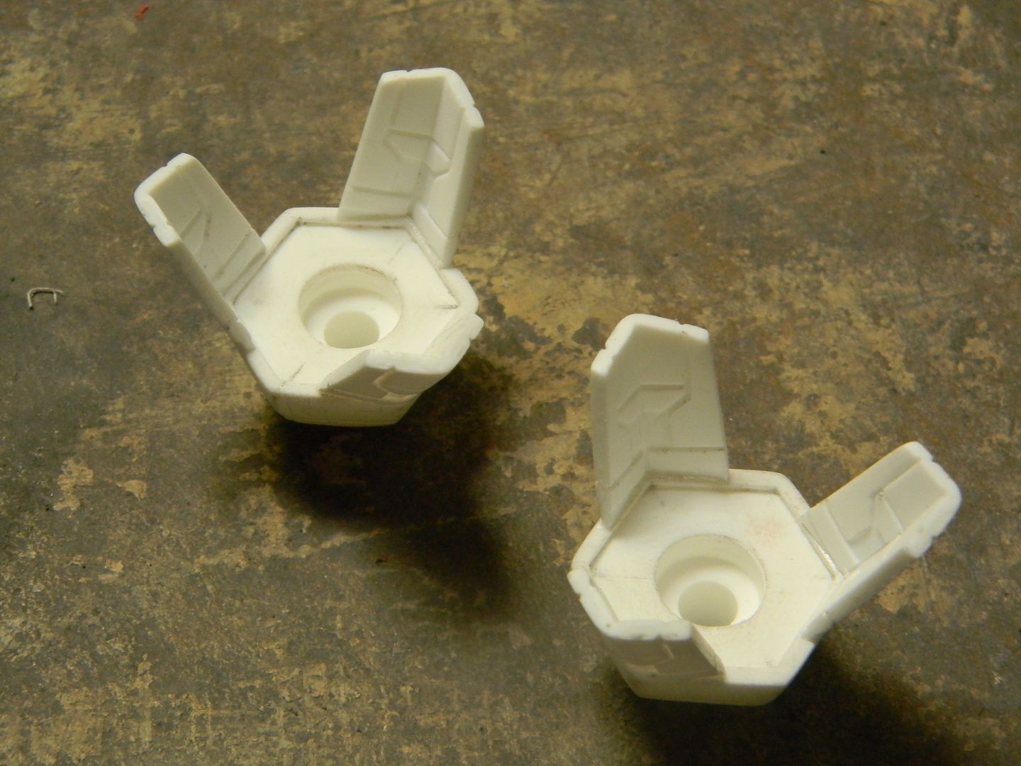
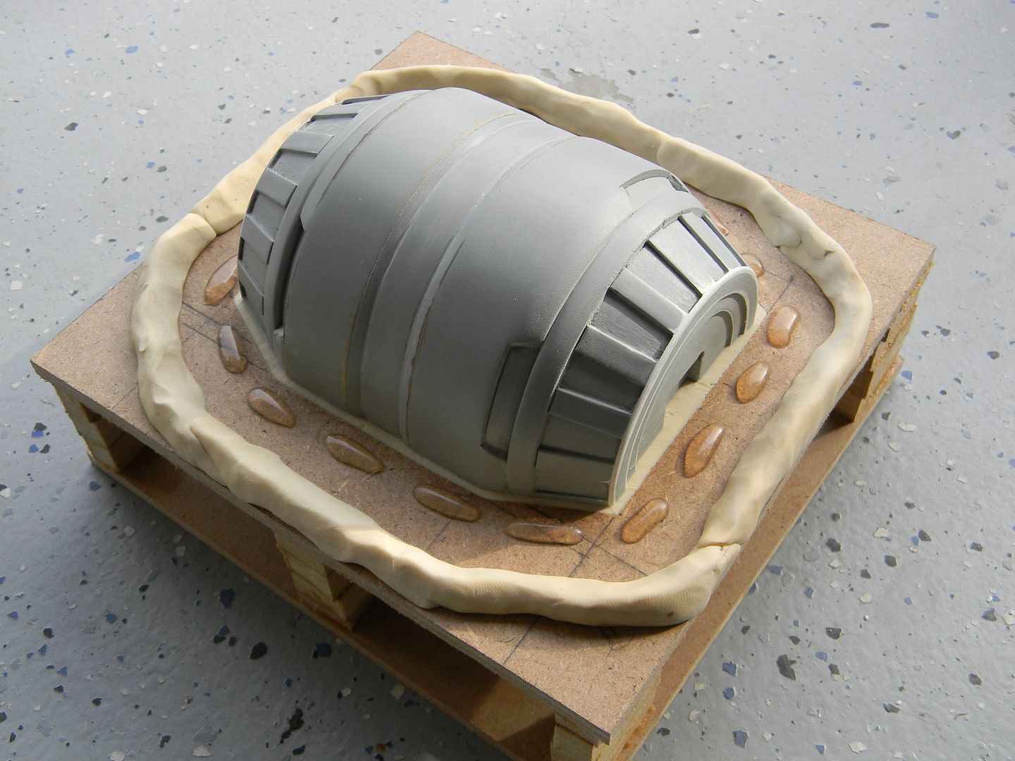
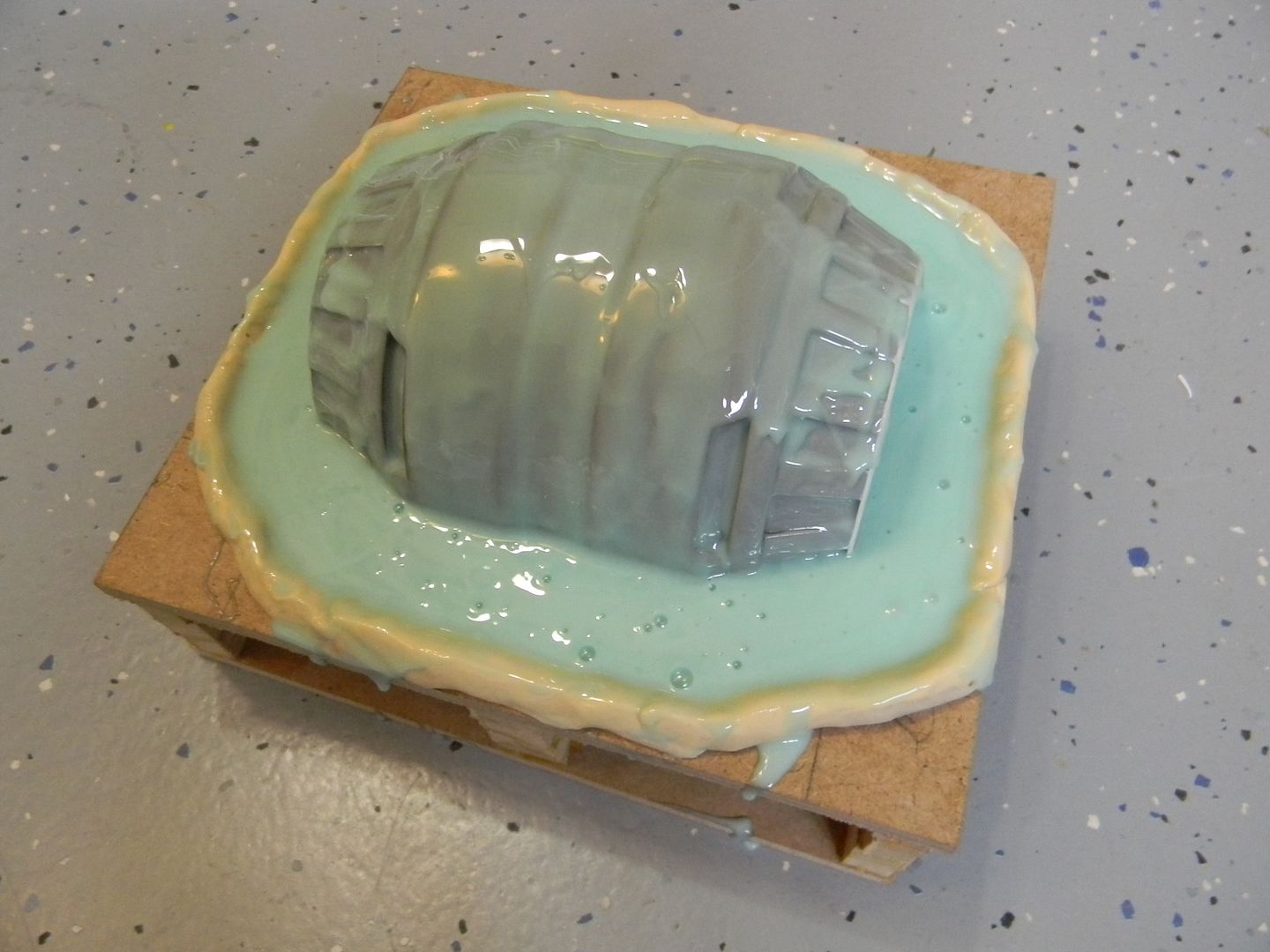
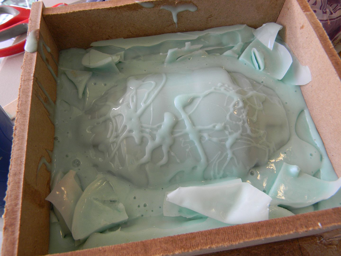
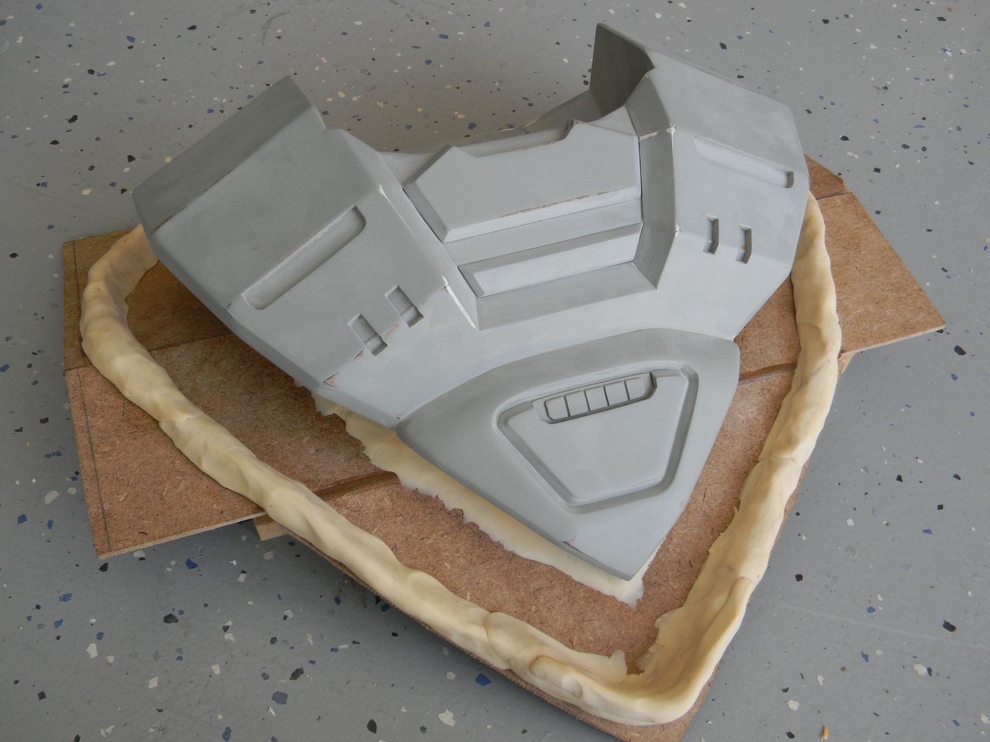
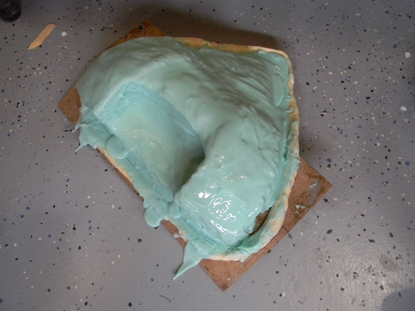
The corner assembly was pretty straight forward as an open face mold. Only problem was because it was a brush on mold, it would need a hard jacket. For this I used plasti-paste from smooth on. There are three massive undercuts, so a hard jacket would lock the part in. The part would then need to be destroyed to get it out of the mold. Then, the jacket could be taken off the silicone, and cut into sections as keys. Since I was in a hurry I didn't want to make a bunch of MDF dividers and do separate applications of plasti-paste.
This is unfortunately what had to happen to make the mold. Good thing it came out okay!
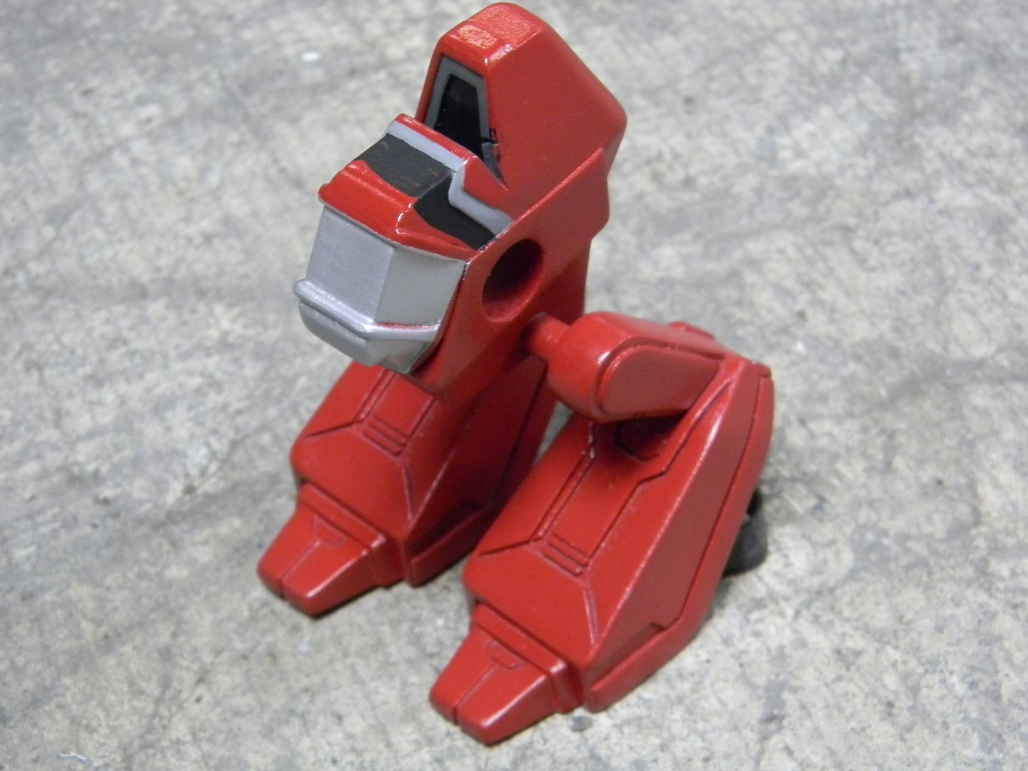
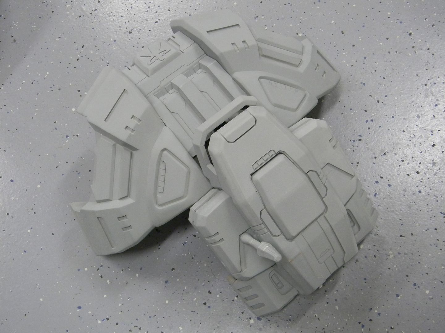
First two corner casts!
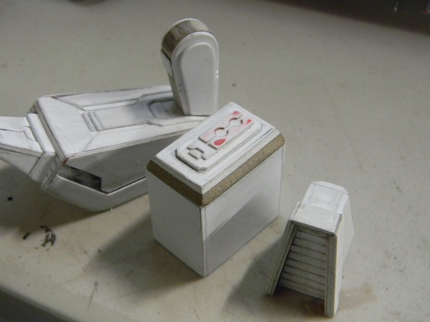
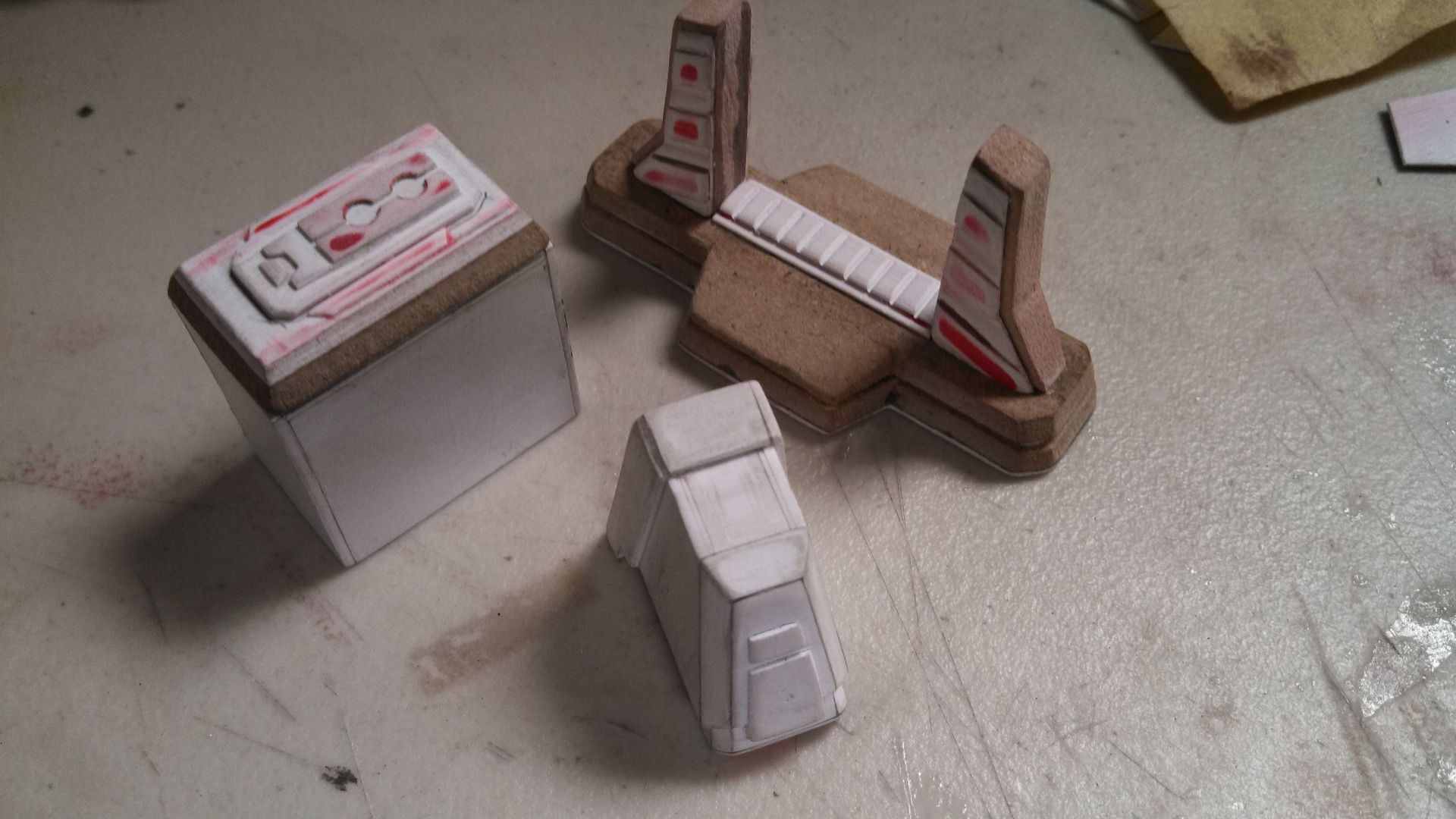
You may have noticed a lot more detail on the command module. All of that was just hand cut styrene.
Anyways, a lot of these were lightly glued in place to test fitment, then pulled apart. The little marks where the old super glue remained were what I used as reference to made adjustments.
This served as a very critical support piece, as these parts pulling on the MDF side modules aren't as strong as gluing resin to resin. It was also cut out later to support the graphics card sticking out of the top.
The command module has some strange intersections and it was a little tricky dremeling it to fit nice and flush and still be easily removed.
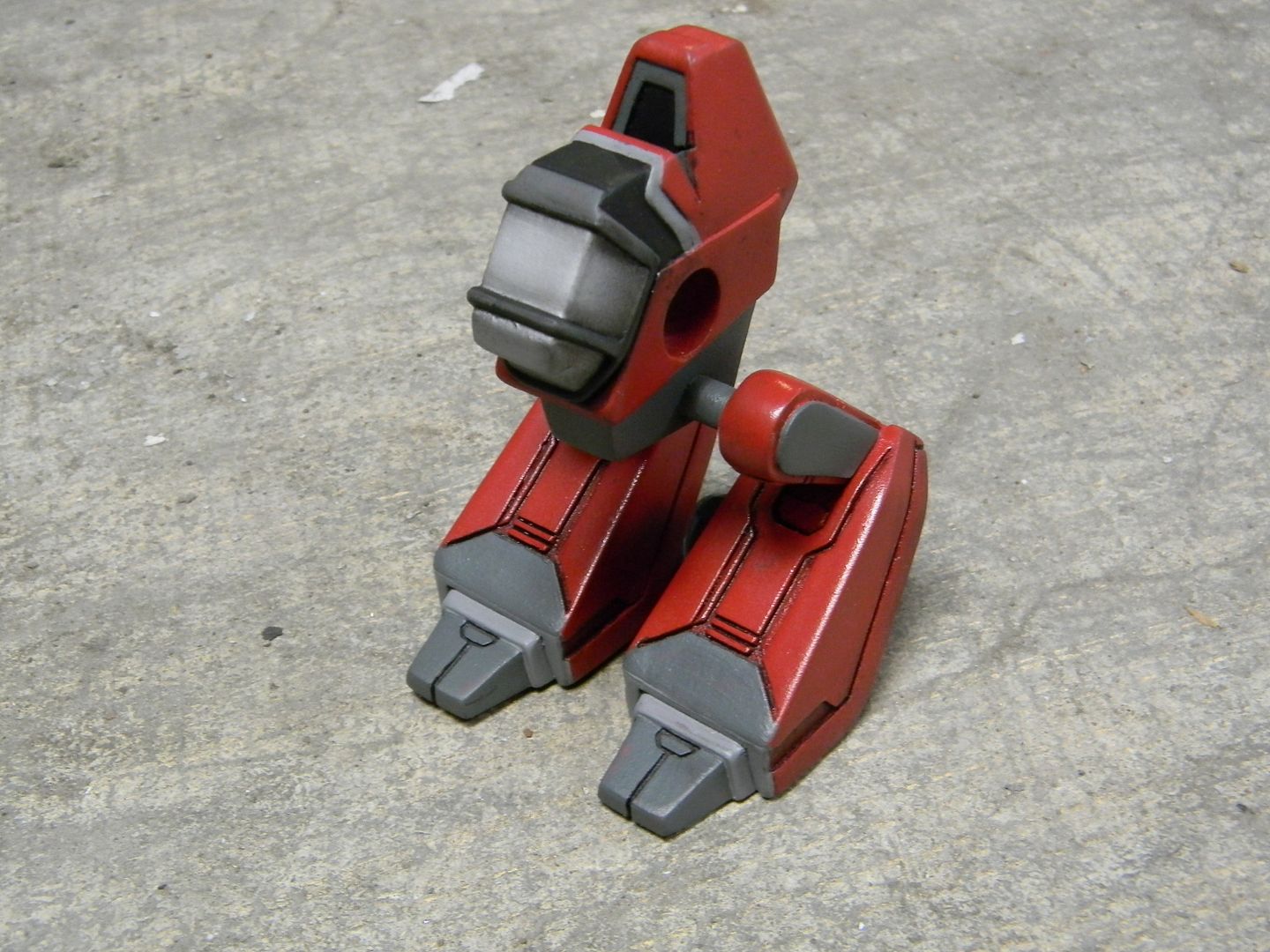
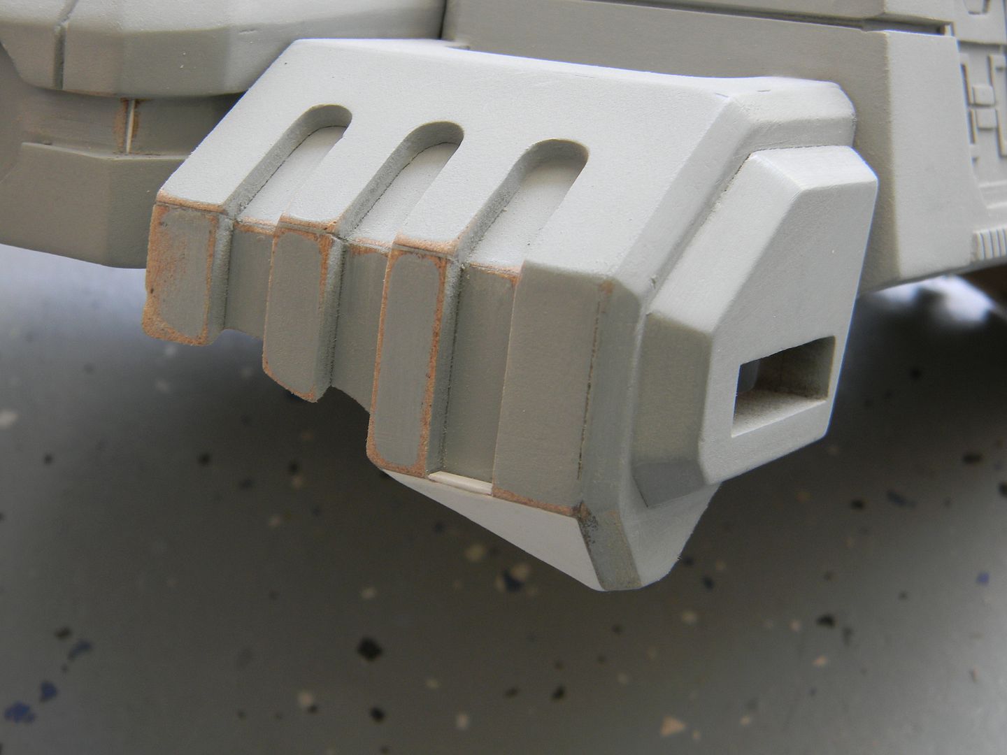
Being somewhat satisfied, I started playing with casting the feet.
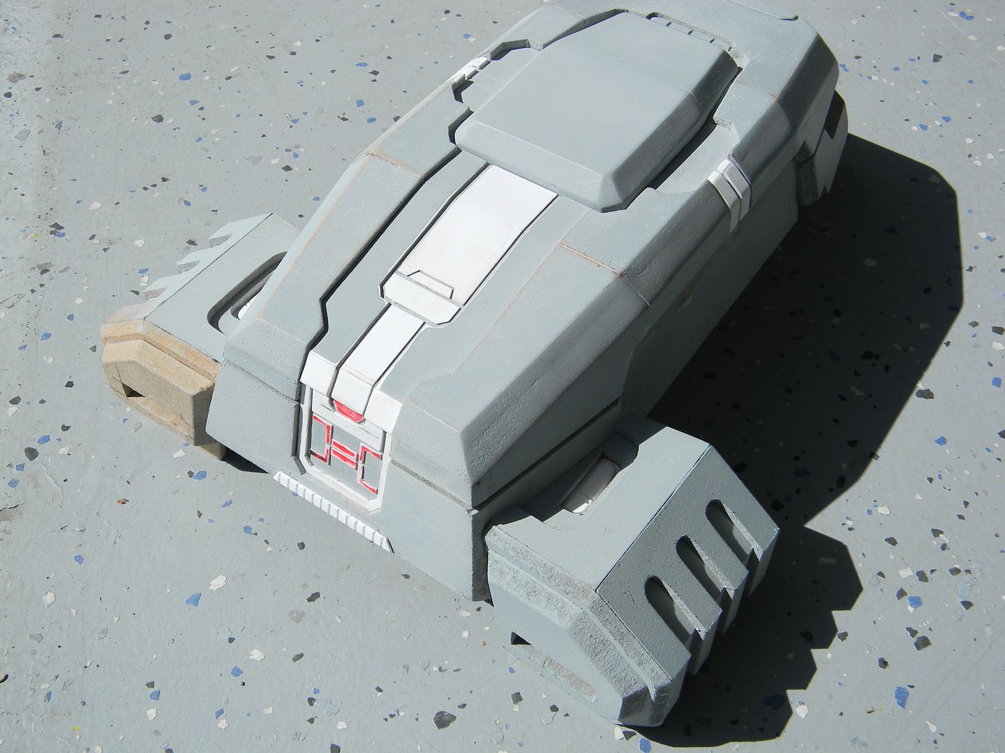
I wasn't very happy with the lower halves of the foot castings, so I used to the top halves of the casts and mounted them to the bottom halves, which were hollow and completely scratch built. It took a good 2 days to fix that error, but the results are nice.
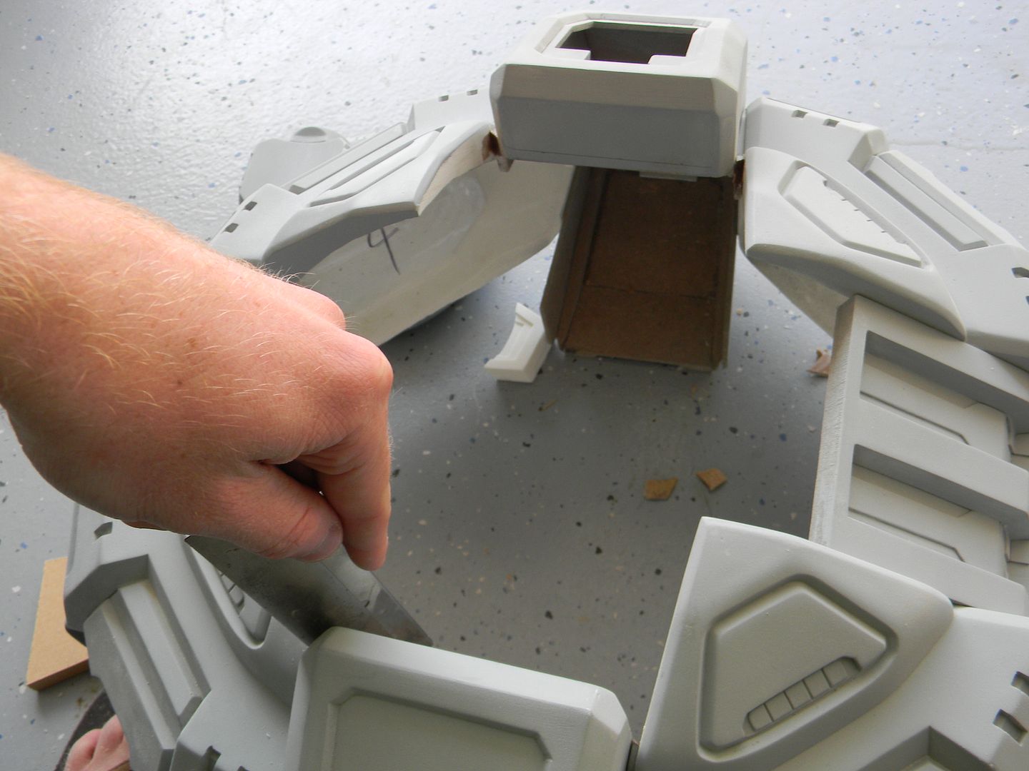
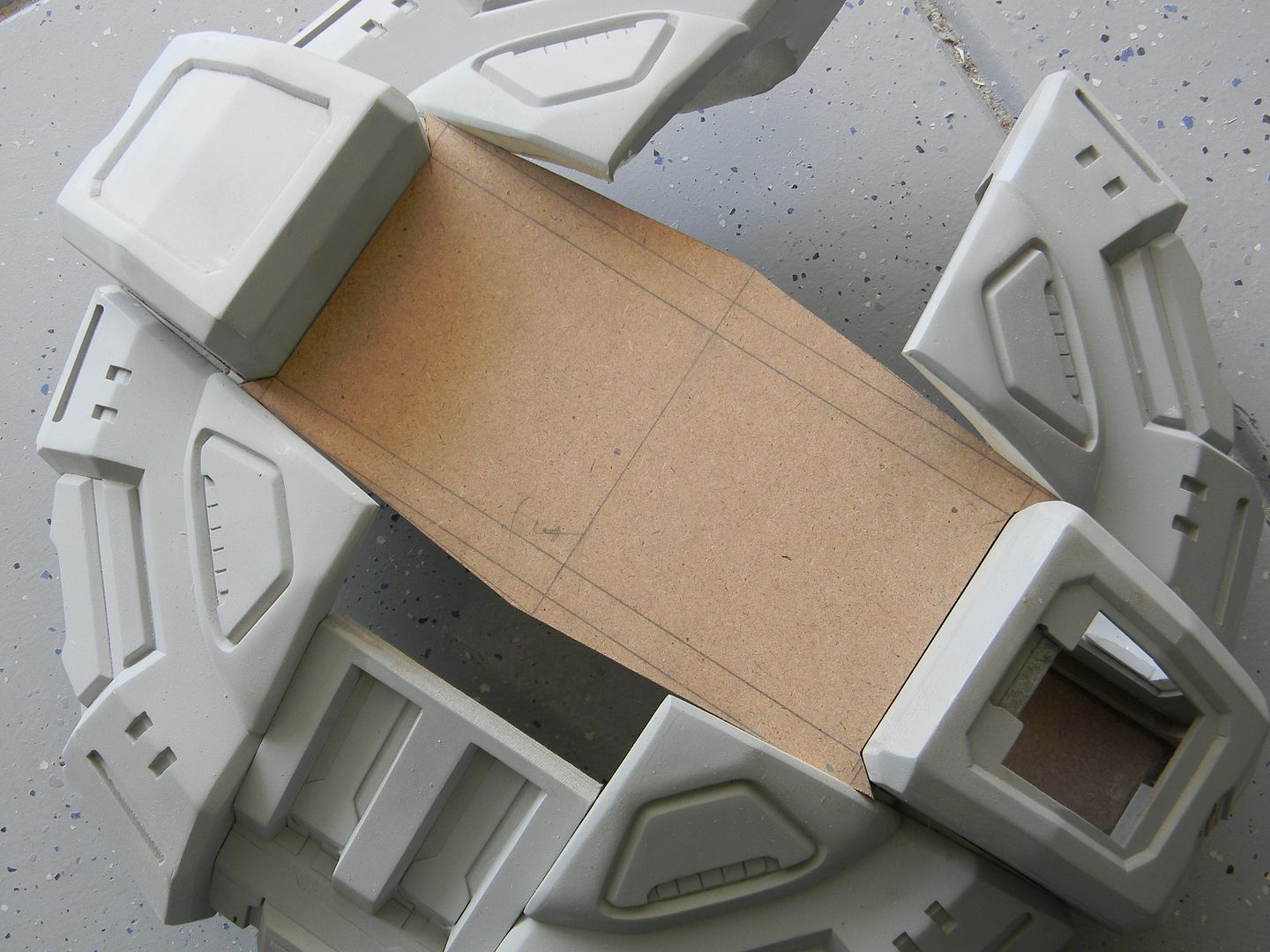
Now that the shell is mostly mapped out, I can close the gap by outlining the thruster housings, which also serve as frame support.
Simple, right?
Not as simple.
I hacked away all of the plastic back here except for a few slivers for the MDF frame to glue on. I needed to save weight as well as allow air flow from the fans. This is where the exhaust fans are going. We'll see those engines mounted up next time, with some electronics in there!